20071007
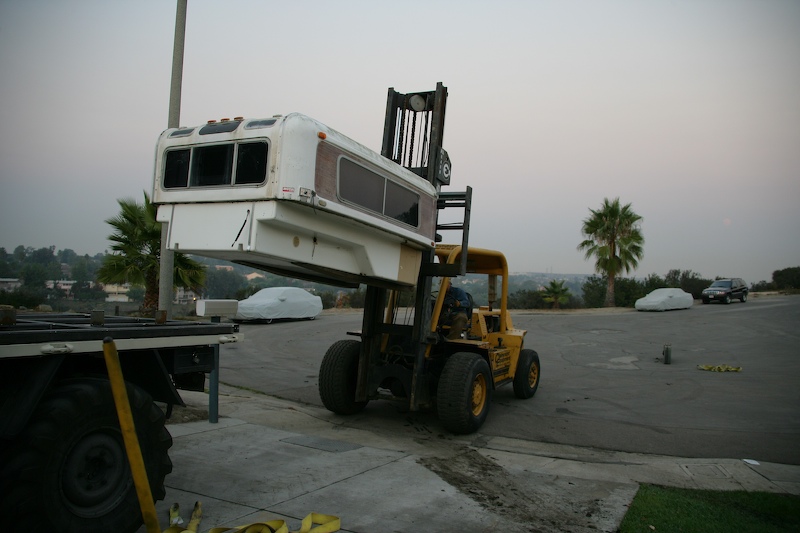
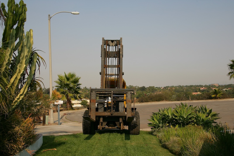
Rental forklift places camper on frame about half way through construction.
More than 3 years ago, I purchased an Alaskan Camper for my mog. But, due to the demands of work and our travels, I did not have the time to be able to mount the camper. During the intervening years, I considered many alternatives to mounting the camper, but it the end, the best solution was to design and build a metal frame that would sit under the camper body. The frame would be bolted to the camper and to the frame of the unimog as well. The corners would have plug in points (not unlike a trailer hitch receiver) that would allow insertion of the lifting assembly. This turned out to be a complex project that required a ton of welding, metal cutting and general dirty work. I bought the camper from a fellow in financial distress for the paltry sum of $600 delivered. New, these are about $20K, but this camper is far, far from new. In fact, the unit has suffered the hands of many and I am not sure which of the internal systems (stove, refrigeration, etc) work, if any. But, at $600 I didn't really care. So, it sat there in my side yard on saw horses for the previous 3 years.
The basic plan was simple: measure the camper and the truck and build the frame in place on the truck bed to insure that it will fit. Then, rent a fork lift and fetch the camper from the side yard and lift it onto the bed of the truck. It was a reasonable plan, but we did encounter some "difficulties". The construction is still in progress, but the really big stuff is complete. There were some tense moments, particularly when I got the 20,000 pound forklift stuck in the middle of my front yard doing massive damage to my landscaping.
Right in the middle of the construction, the fires broke out in San Diego and LA areas. I continued to work outside for several reasons, the biggest being that I could easily see the canyon and should something happen that would require us to evacuate on short notice, I would see it coming rather than hearing about it on the TV. Plus, I wanted to get the job completed ASAP since it is hot, dirty, hard work.
The photos below show what happened.
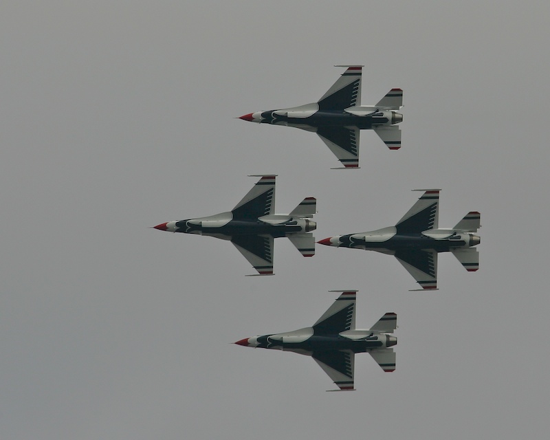
The Miramar Air Show occurred early in the initial construction process and since I was outside with my camera, I got these shots of the USAF Thunderbirds as they performed. Since we are pretty close to the airbase, the flight path of the jets was quite near my house. Here they have the belly of the aircraft toward me as they execute a banked turn in formation.
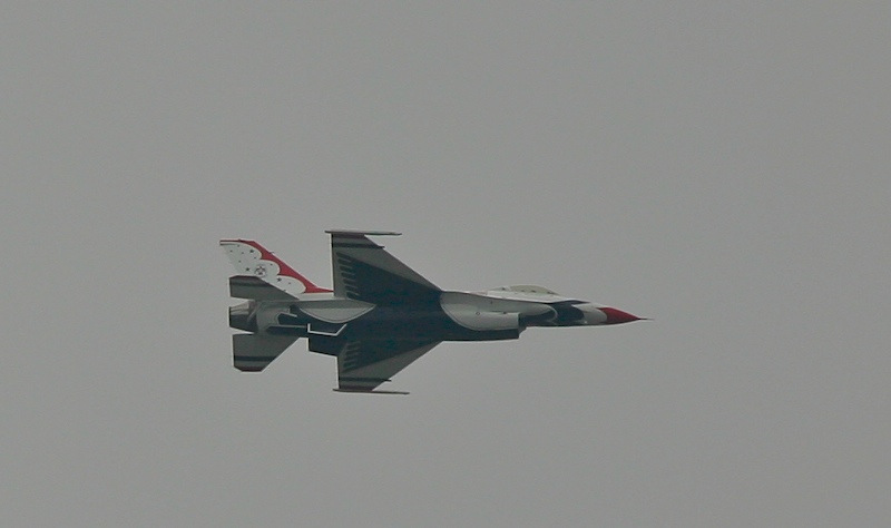
A side shot as one of the members fly's by solo.
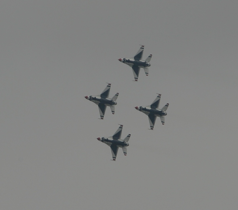
Part of a loop in formation.
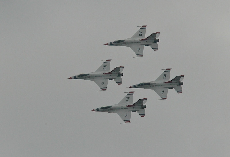
Another banked turn, this one with the top side facing us.
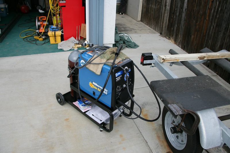
One of the first things that happens during a project of this scope is a trip to the store. In this case, I bought a MIG welder setup, a cutoff saw and some misc. support equipment. Here is the Miller Welder I got and it performed great.
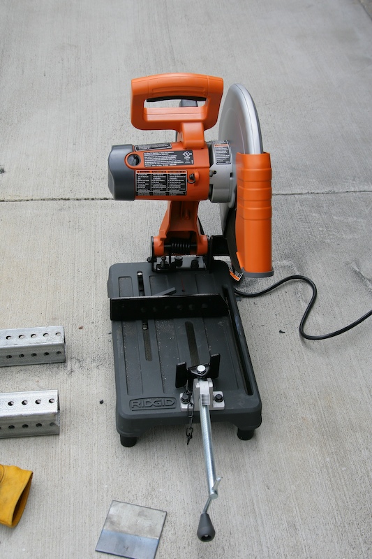
This little cutoff saw will get some hard use. Note the nesting tubing on the left that will be used to build the lifting assembly.
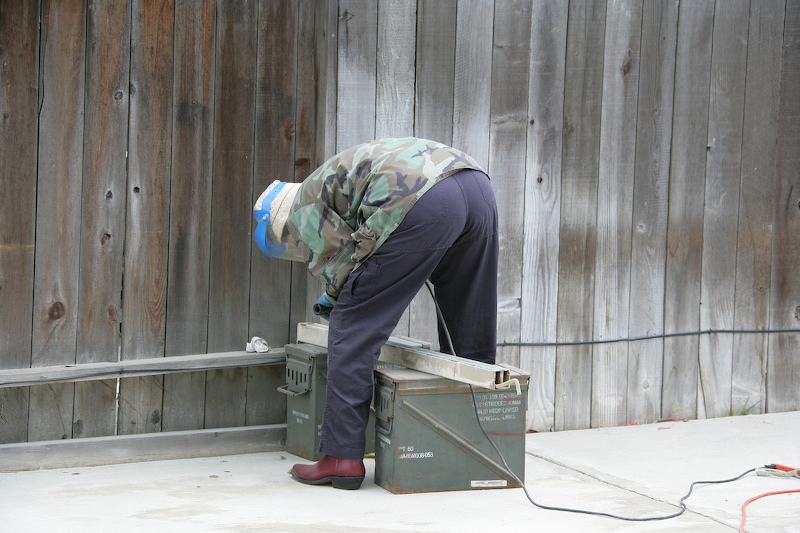
The mog came with these nice spars that extend out from the frame to allow the tailgate to sit horizontal. But, when I had the frame powder coated years ago, the coating made easy use of these impossible. So, the only solution was to remove the powder coat. Here Kathleen gets up close and personal with Mr. Angle Grinder with wire cup. It took her several hours per spar to get sufficient coating removed. That stuff is quite robust.
Here, the spar is in place in the extended position. Note that it can retract under the bed and it has trick spring loaded pins that hold it in place. In this configuration, the tailgate can come down and act as a "porch" for the camper.
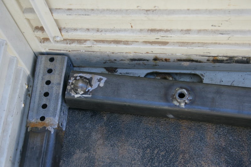
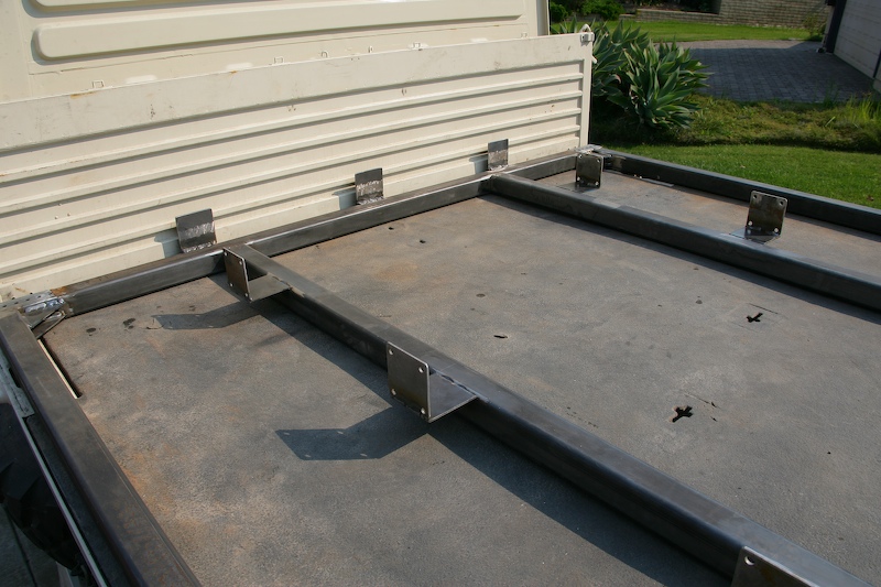
One critical design issue is getting the frame aligned on the mog bed, both initially and after removal. Since the bed had a number of attachment points and lined holes (for cargo canopy hoops), I used these holes as the registration points. At the steel store, I found these hemispherical cups that just fit into the hole, thus providing a way to allow the parts to mate. When positioned to within one radius of the cup, the frame will self align. It works good.
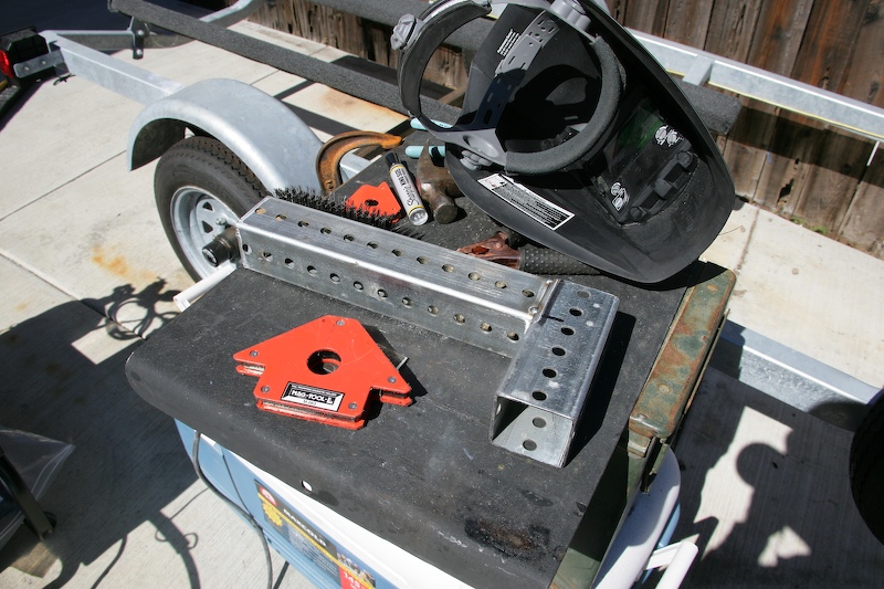
Fabricating the lifting attachments for the corners. These are made out of nesting tubing and the punched holes will provide a flexible way of obtaining the connect alignment and length.
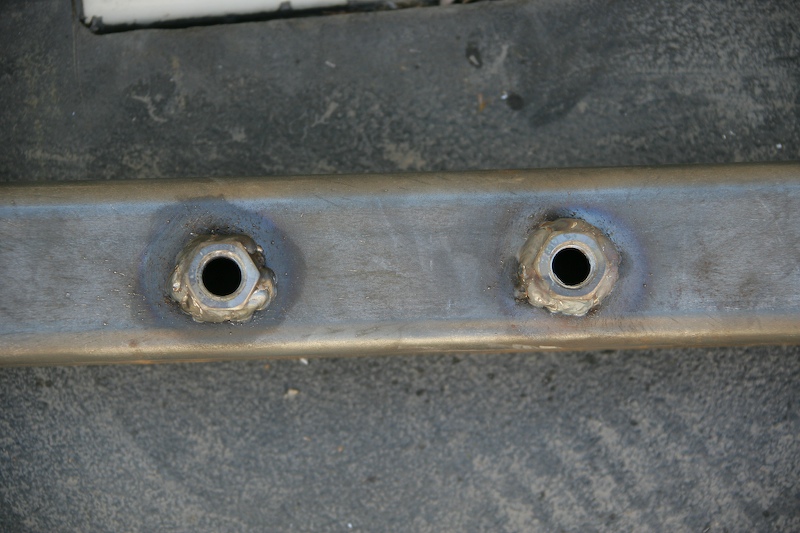
Mounting bolts for the frame. Here, I carefully positioned the holes to match the stock holes in the mog frame and then welded nuts on to provide threads.
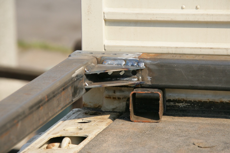
A view of the corner components before assembly. Note that the bed walls are up. The part on the right will be turned upside down before being welded into place. The part with the holes will act as the receiver for the lifting assembly.
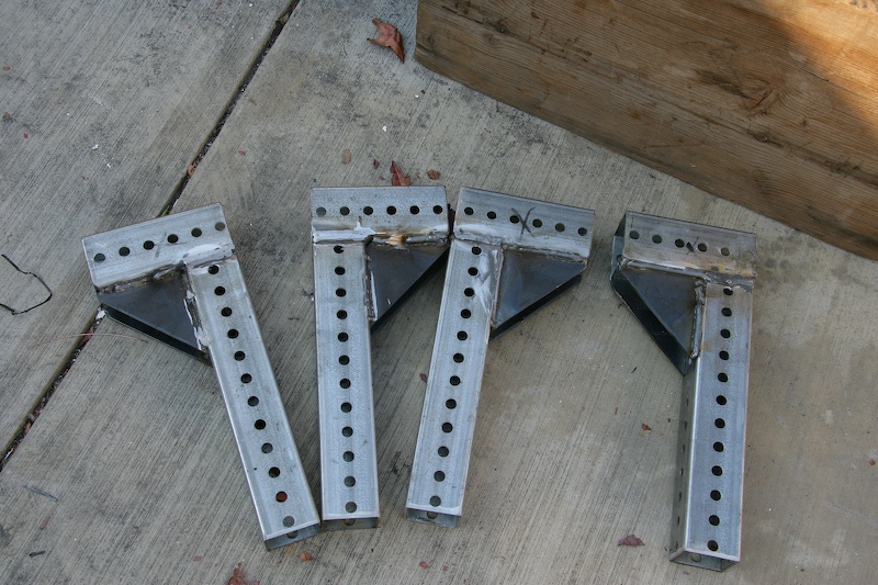
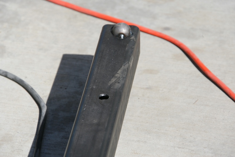
These corner assemblies plug into the frame to provide a lifting point.
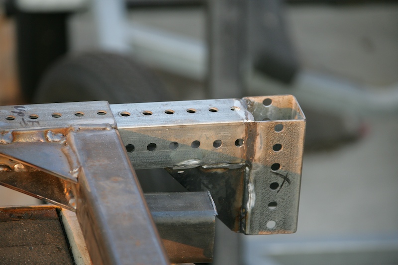
Assembly of the corners. Note the double gussets in the corner for stress.
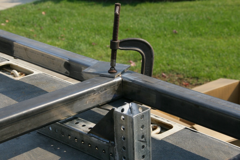
Attaching center supports.
The inside of the front driver's side corner. Note the positioning holes in the bed.
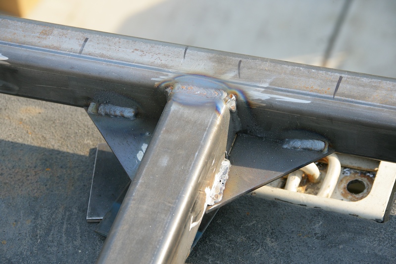
Cross-bed support with gussets and one very shitty weld. Throwing a good bead is not all that difficult if you have a steady hand (which I do not) but it does require CLEAN, CLEAN, CLEAN metal. No grease, oil or rust. That rule was hard learned and many welds were ground out (like the weld to the right of center with the inclusions).
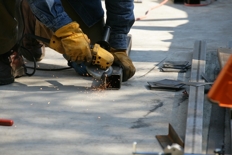
Preparing an end of the tubing for a weld with the angle grinder.
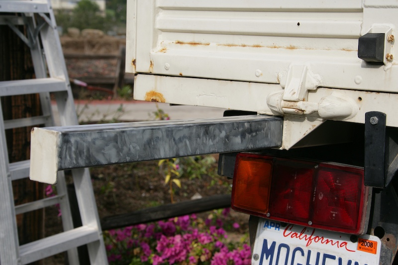
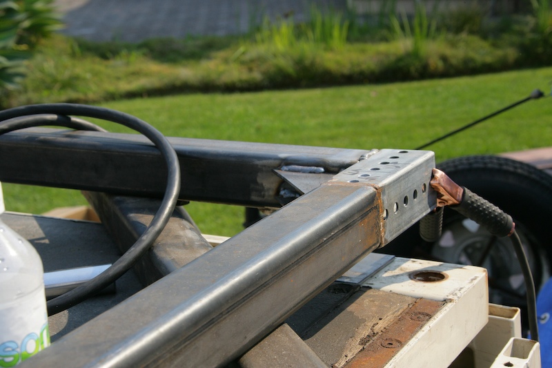
Corner assembly in place to demonstrate how it will work. The vertical tubing will accept the lifting leg with jack assembly.
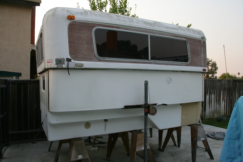
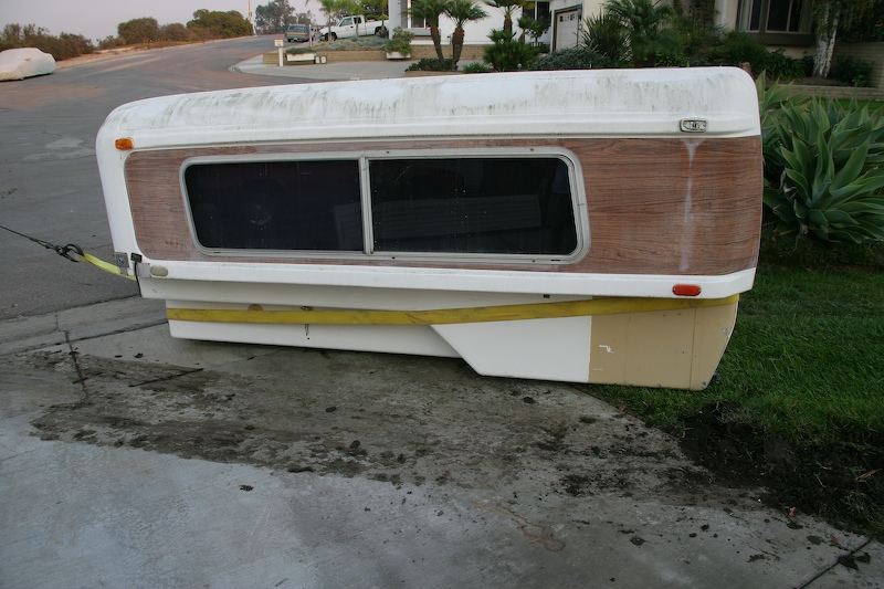
This is a side view of the Alaskan camper with top elevated. This is the stationary configuration and the top lowers when you travel. The saw horses support the camper about 30" off the ground.
This is a big forklift. But, big is heavy. The rental folks told me that this was a "rough terrain" lift, and therefore should be able to accommodate the front yard easily. Not.
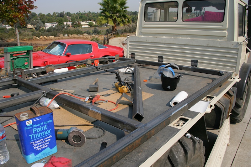
Completing the final assembly on the frame.
Ready to accept the camper. Note the plates that will be used to provide lateral support for the camper.
It is not stuck yet, but give it about 2 feet.
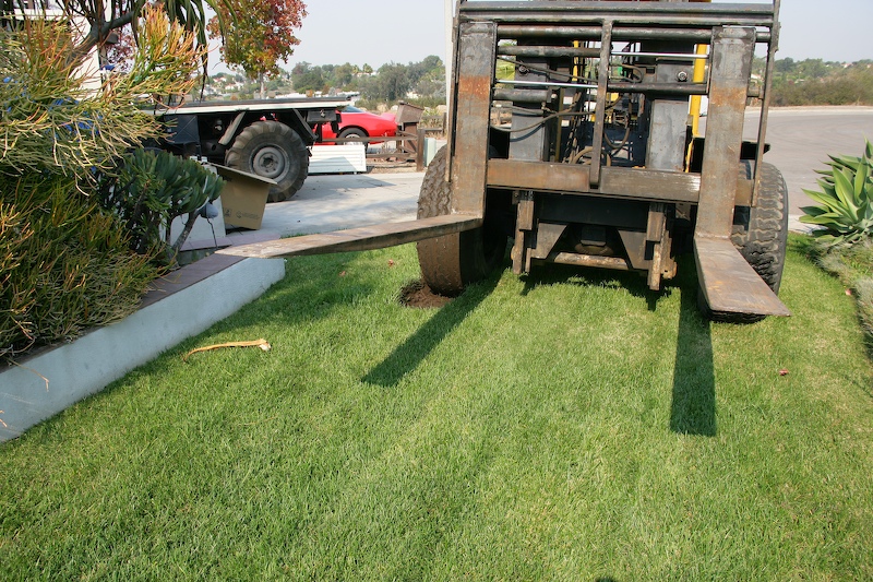
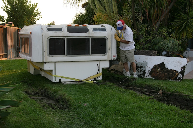
The wheels just spun on the mushy grass and dug a nice, deep trench. We had to tow the rig out with the hydraulic winch on the mog. Twice. Note the thrash marks under the left wheel.
We finally gave up on using the forklift to get the camper out of the back yard. We built a ramp and then used the winch to skid the camper down the ramp onto the ground from the saw horses it had been on for the previous 3 years. Then, we winched it out to the front yard. As a side note, the camper weighs 2,000 pounds, plus or minus a bit according to the manufacturer's specifications. Here, Kathleen operates the hydraulic winch in the mog.
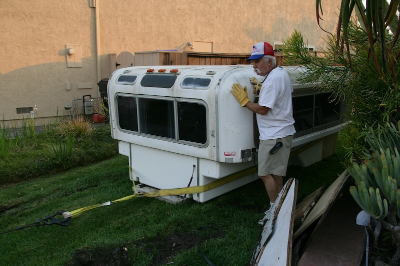
My neighbor Terry assists with the skidding operation. Note the rut in the grass and note the materials that we used to attempt to prevent the forklift from sinking into the ground. Also note the plastic table that we used as a skid to protect the front and underside of the camper bottom.
Those are some big ruts, perhaps 8 inches deep.
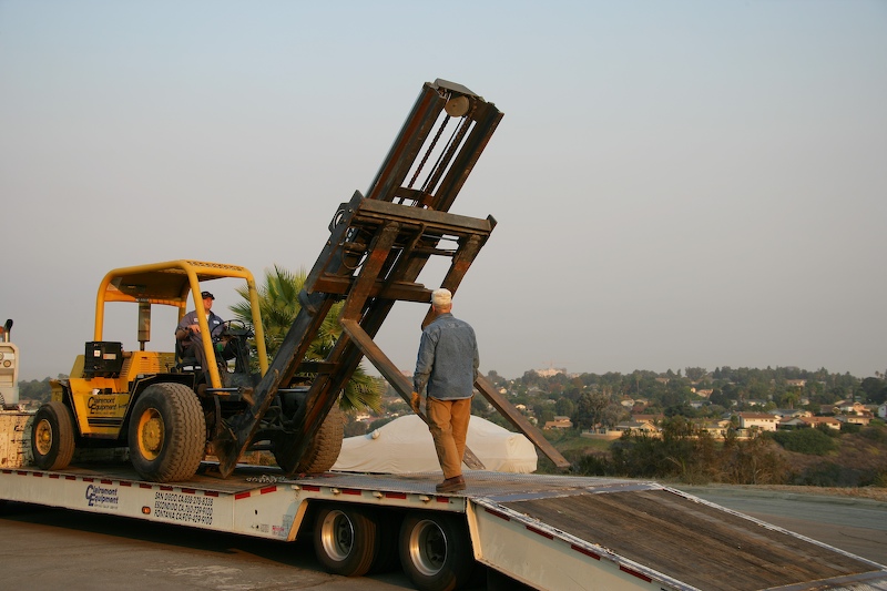
Once we got the camper to where the forklift could pick it up, the task got much easier.
The lift was done in two parts. First was to turn the camper around to the correct orientation and the second was to place it on the truck. We did encounter some challenges like the forks not going wide enough to straddle the camper and the folks not going close enough to provide clearance for the mounting tabs, but we worked around them.
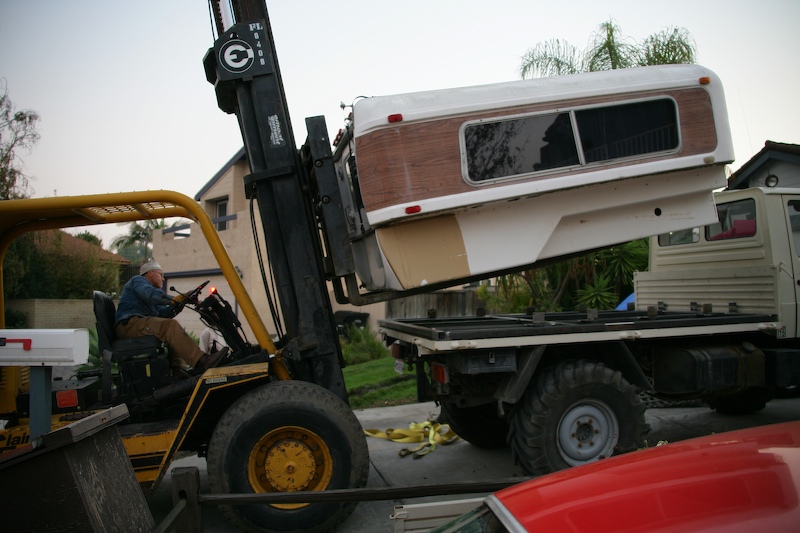
Getting the angles correct was critical. The lift has the ability to move the load left and right using the hydraulics, so that was not as difficult since it could be adjusted via controls.
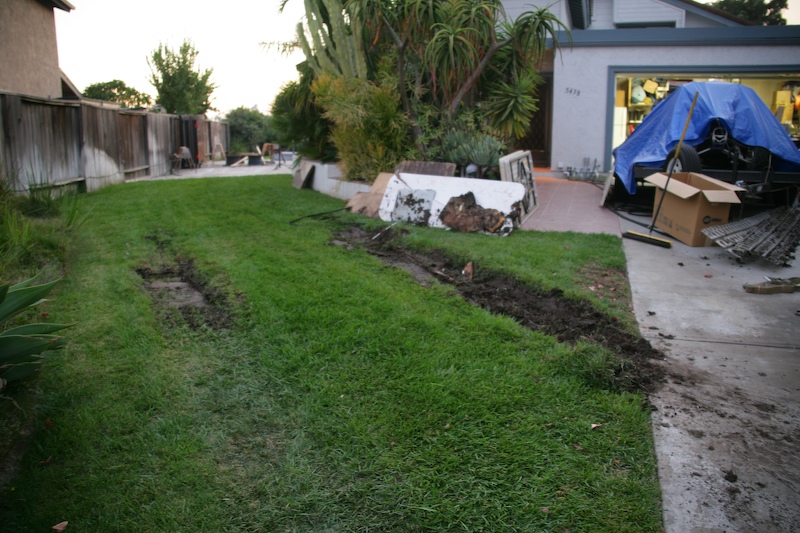
A pretty well destroyed lawn. The good news is that there are honeycomb plates under that grass that prevented the forklift from getting really stuck. Like to the frame. But, it did make a major mess. The clay that came with the sod is like peanut butter and is very, very slick. The tires spread the clay-based mud everywhere in the driveway and street.
The camper in the bed. Note the clearance between the sides of the camper and the bed walls. This area will be used for "dirty" cargo like firewood, diesel cans, etc. A Honda 2KW generator just fits between the end of the camper and the side wall. Perfect.
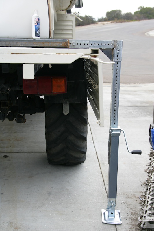
A close-up of one of the jacking assemblies. The bolts that are visible are used as blocking pins to keep things from shifting around. There are 4 critical parts: the frame, the corner assembly, the leg and the jack. These jacks came from Northern Tool online for about $60 each and they can lift 5,000 pounds per corner, more than enough.
This was a big project. At this point, we are 2 weeks into it and are still doing actions to get things completed. Yesterday (20071029) we completed the attachment of the camper body to the mounting tabs and took the truck for a road test. The camper is not really an issue for the mog as it is well within the weight rating. In several respects, the truck runs better with the camper on than without. One reason is the weight makes the ride smoother and the other is the camper makes the truck a bit more aerodynamic and therefore rolls better at speed.
After completion of the steel work, I started on the interior issues. As I mentioned above, the previous owner was a bit "hillbilly" and his attention to detail (and safe construction) was somewhat lacking, so I had to "undo" most of his work. I removed and replaced all the interior wiring, most of the plumbing and the refrigerator and replaced it with marine-grade components.
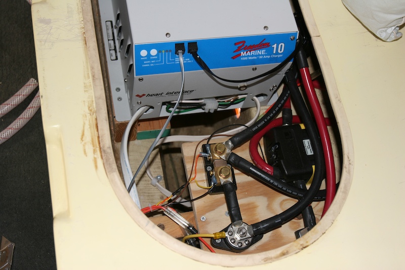
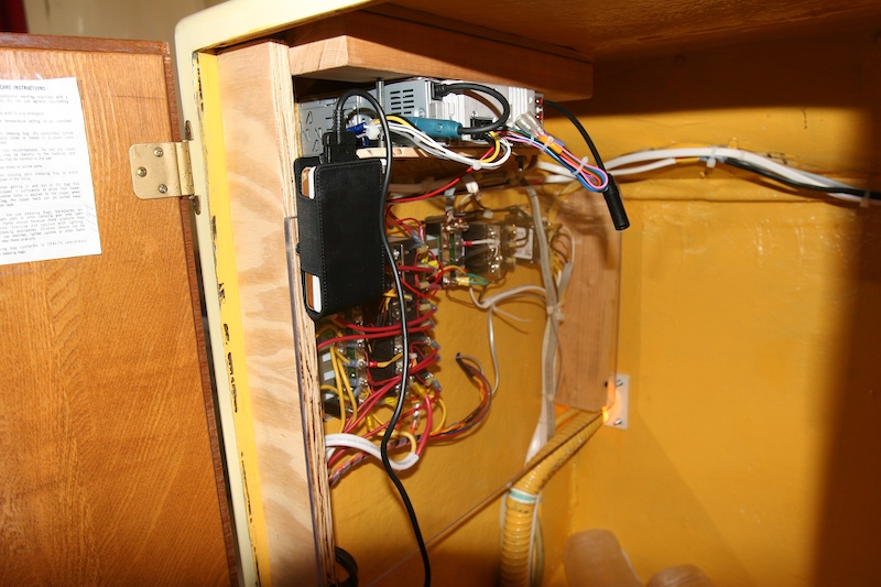
This photo shows the electrical bay with the converter-inverter and high current DC wiring. The converter-inverter provides 1 kw of AC power from the battery array that is mounted outside the camper. It also acts as a batter charge controller when the camper is connected to "shore power". The system worked as advertised and allows separation of the main unimog battery from the battery array that powers the camper so usage of the batteries does not prevent starting the truck the next morning. Getting all this stuff mounted under the seating area was tough as it barely fit and the working conditions were cramped and difficult. The item in the center of the photo is a high-current shunt that is used for current measurement. All power cables in this installation were 1/0 gauge marine grade cable with shrink wrap on all connectors.
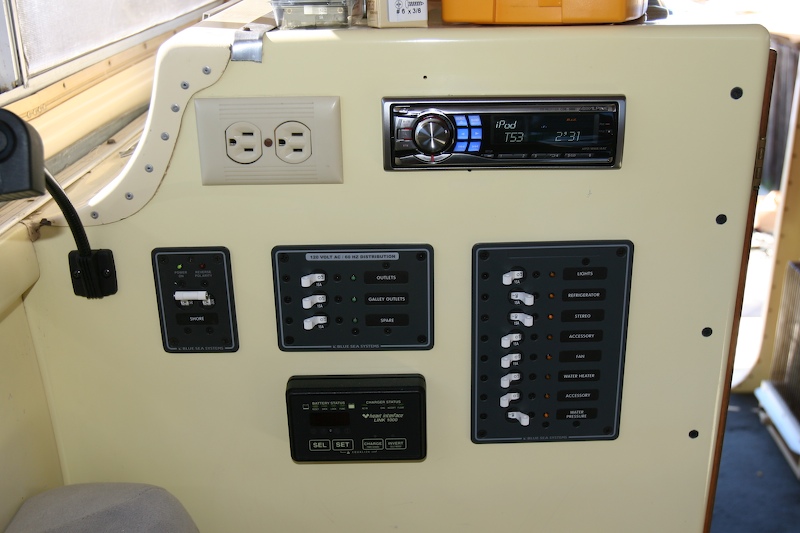
After the power converter and associated wiring was installed, I installed the power control panel and stereo. The top two items in this photo are obvious - an AC power plug and an iPod-capable stereo. Below is the 30 A main shore power breaker, the individual AC circuit breaker/switch panel and the DC circuit breaker panel. The panel on the bottom is the remote control for the converter-inverter. The remote panel also measures cumulative amp-hour usage of the batter array to assist in power management.
This photo shows the back side of the breaker panels and the mounting for the stereo. A cut and installed a plexiglas panel to provide mechanical separation and protection for the wiring. The iPod is hanging in the pouch.
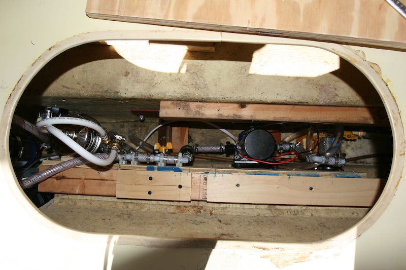
Under the other seat in the dinette, I mounted the new plumbing. Jed (my name for the hillbilly owner) had done a really rotten job of plumbing, so I ripped it all out and re-did it. I have a 3 gpm demand pump that feeds twin water filters. The first filter is used to strain out "the big stuff" when filling the tank. The second filter, visible on the left with the white hoses, is a bacteria and virus filter that provides great tasting water from the on-board tank. The water is as good tasting as bottled water and just a bit better than our reverse osmosis water at home. We can, if need be, fill the on-board tank with contaminated water and rely on the filter to clean it up. All the plumbing is mounted on plywood that will allow removal of the entire sub-system should that be required. I hope not as the plumbing was much worse than the electrical in terms of cramped conditions.
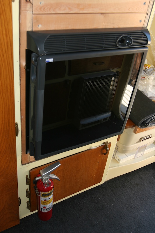
I also ripped out the old propane-based refrigerator. I never did establish that it worked because it did not matter. You cannot run propane when you are in motion, so it was a non-starter. I replaced it with a Norcold 2.1 cu .ft. 12V/120V unit that will operate 30 degrees off level. This unit has a bigger internal capacity than the unit it replaced but the footprint is smaller which required a bunch of woodwork to get the mounting robust. The 2 2x4s that comprise the face plate are visible at the top of the photo. Also visible is the portipotty and mounting on the right side of the photo.
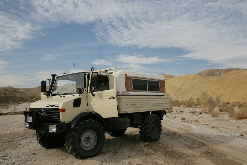
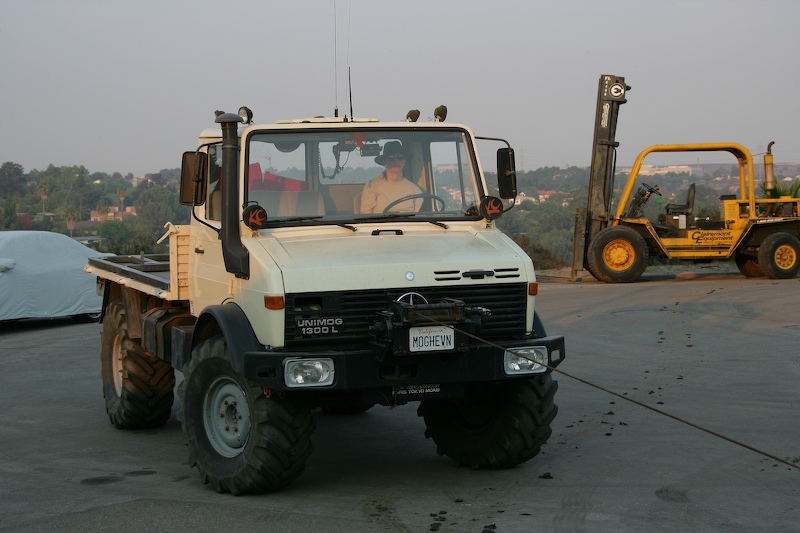
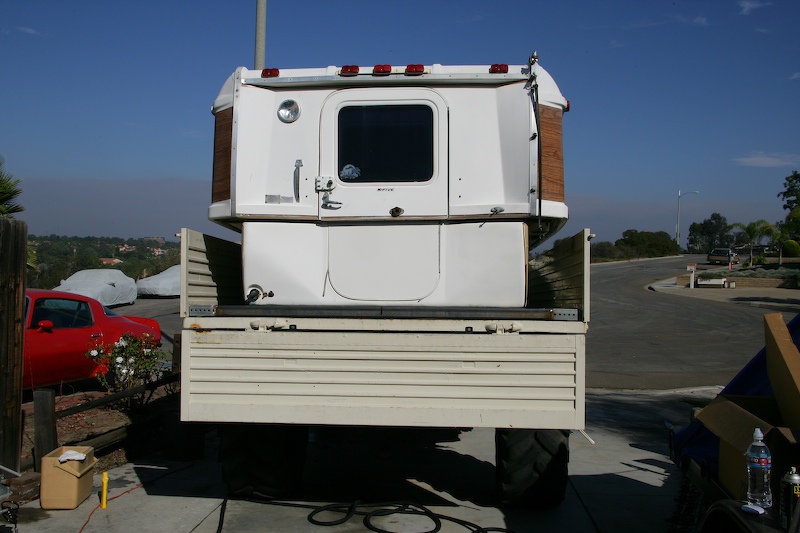
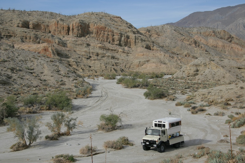
After many weeks of effort, we were finally ready for a field test. We checked the weather and were promised a nice hot day in the desert, so we paced our stuff and left. Our destination was Fish Creek Wash in the Anza-Borrego Desert State Park east of San Diego. The photo above shows the Unimog with camper attached in the "travel configuration" with the top lowered.
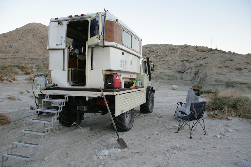
Once we reached the camp site, we raised the top using the hydraulic lift system. Now this is a full height camper. Note the Honda generator on the back left of the bed that can provide 2 kw of (reasonably) quiet power if needed. Also note the folding steps and propane bottle connected at the back left. The camper has a internal heater as well as a 3 burner stove top.
Here is a parting view of the camper in Olla Wash where we camped overnight.
Our test run was flawless. We chose our date based on the weather and knew that a big rain storm was moving into the area the next day, so we only planned to stay one night. But, that was a sufficient time to prove that all the sub-systems operated as expected. We purchased a new 2 person sleeping bag that was so warm that we did not need the heater. The heater was proved several weeks earlier on a limited-scope test run, so we knew it would work if needed. The camper provided us with a bunch of conveniences that were very easy to get used to including fast setup and tear-down as well as a warm place out of the wind.
There are still actions to complete, but most of the big stuff is complete. Like most of these tasks, it was more work and more expense than expected, but it has proven worth it (so far). One of the items that was on the list but not yet constructed was a water heater. I looked at the commercially available propane-powered "flash" heaters (i.e. a heater with no hot water storage tank) and they were wimpy. Those that we of sufficient thermal capacity did not provide sufficient water pressure/flow or had poor temperature control. Since idle hands do the devil's work, I decided to design and build one myself. The short story is that the design called for inter-locking helical coils and about 50 feet of 1/4" ID copper tubing, a powerful burner and a frame/sleeve assembly to encapsulate the assembly. The photos below show the essential parts of the heater.
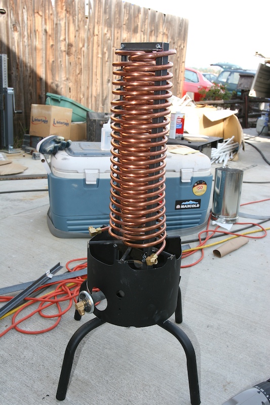
To fabricate the coils, I purchased copper tubing and fittings at the local hardware store. I mounted a small propane bottle in my vice and used it as the mandrel for the bending. Bending the tubing was easy and only took 10 minutes or so per coil. The photo below shows the completed heat exchanger assembly with the interlocking coils.
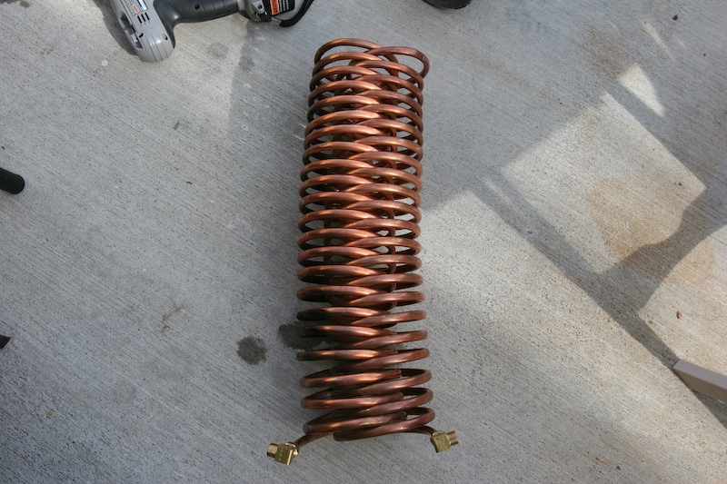
Heat exchanger coils.
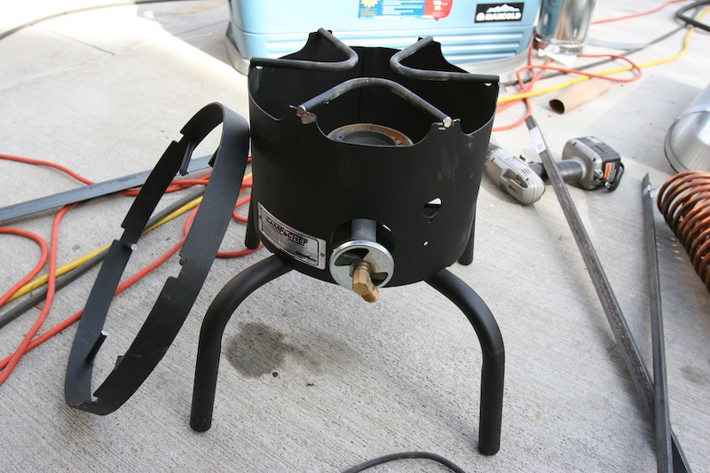
Camp Chef burner that was chopped to provide the burner assembly.
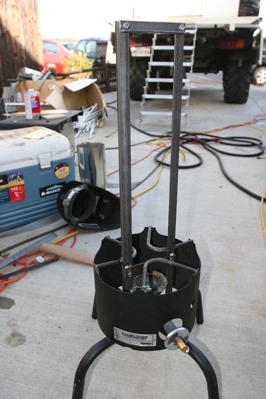
Mounting tower for the coils welded onto the burner assembly.
Heat exchanger mounted on frame, less plumbing. The top frame member actually compresses the coil assembly to insure good thermal contact and stabilize the assembly from vibration during transport.
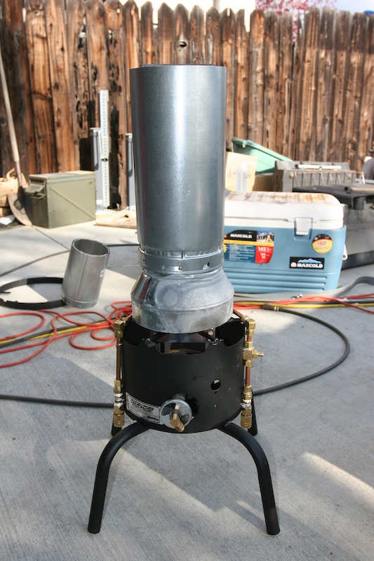
Finished and tested assembly with quick-connect fittings. Note the vent duct used to channel the heat flow and protect from wind. The needle valve on the right side of the assembly is the fine control over water flow.
The testing of the heater exceeded my expectations. Early in the design, I tested a single coil on my camp stove. This is a BIG stove with a big burner, but the heat output was not sufficient for my tastes. So, I migrated to the interlocked coil design. That, of course, improved the effectiveness of the heat transfer, but it was still not sufficient. My goal was to have full temperature rise to 120 degrees F at full flow (about 2 GPM). The burners on my stove were rated at about 35,000 BTU, so a bigger burner was needed. I found a burner at REI for about $65 that puts out 75,000 BTU and was actually MORE than was needed. The rig is so efficient that great care is needed when using it because the burner is so powerful. The burner is controlled with needle valve, so fine adjustments are easy. Notably missing from the above photos are a pump. This design uses the diaphragm pump mounted in the camper as the water source. The drain hose has a quick connect that allows easy attachment of the connecting hoses. I used an el cheapo shower wand that I got at Home Depot for $15 as the shower wand. After I added the quick connect fitting, it was ready to use.
Hot water flow from the heater is nearly instant. In my tests, the rig will produce a steady stream of scalding water at the full 2 GPM flow rate and 50 degree initial water temperature. And, as a bonus (or a risk if you are not paying attention) there is a ton of head-room on the burner should high-temperature wash water be needed. Or water for pasta, or soup. But, if you throttle back the burner, you can get the water flow from scalding down to tepid or any place in between if desired.
All in all, I was very please with the heater design. It is neither small, nor light, but what it lost in being svelte, it more than made up for in effectiveness. Cabelas had a similar heater for $400 and it got mediocre reviews. I paid about $150 in parts for this rig, plus my time, but it is far more capable. You should note that my design leverages off an existing pump in the camper whereas the Cabelas rig is a fully self contained system including battery for the pump.
Only the roof rack remains to be done.