Initial Report 20080525
UPDATED 20080531
As reported in a normal trip report on our recent trip to southern Utah we suffered a significant mechanical failure of the bolts that hold the Unimog's transmission assembly to the frame. This required us to terminate our trip early and return to San Diego to effect a repair. I went to my buddy Kai's place and we undertook the first actions to get this issue addressed.
The photos below are what we saw.
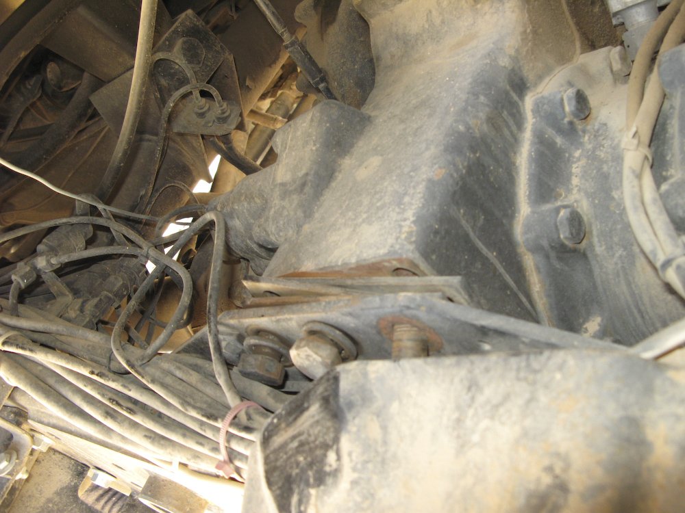
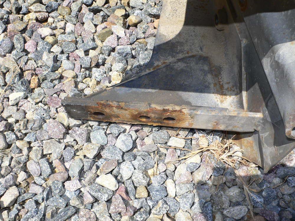
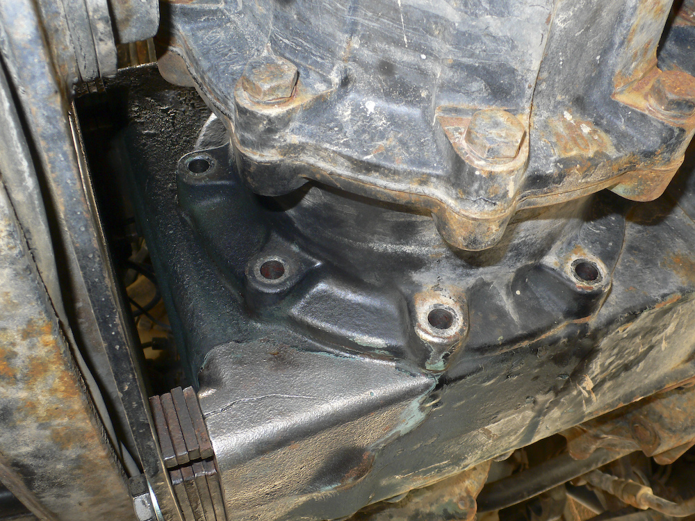
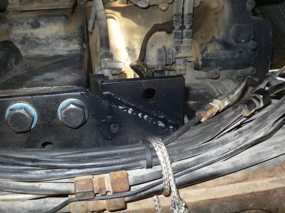
Here is a view of the original failure. This photo was taken on the trail.
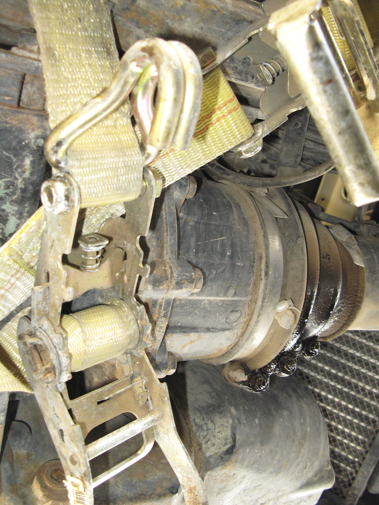
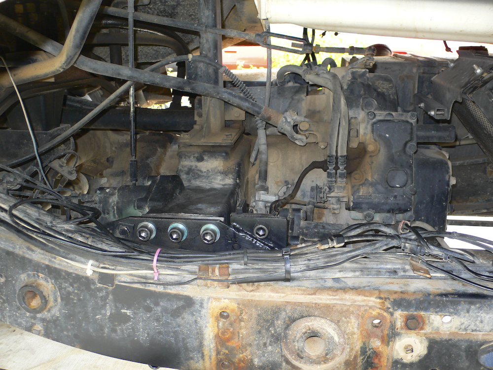
This is a photo of the original fix that used 2 big ratchet straps tightened to "C sharp".
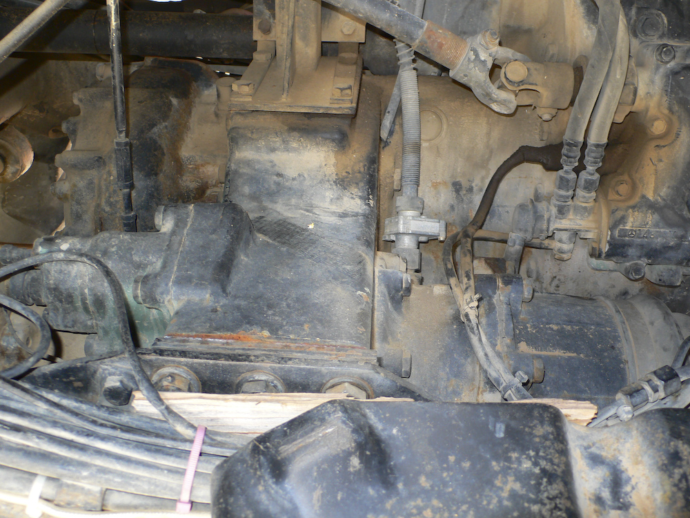
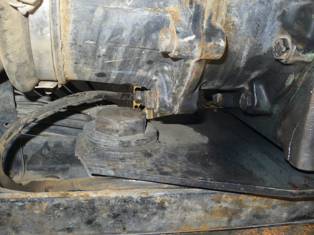
The action here is to get the bolt stubs that are broken off in the transmission case out and get them replaced with new bolts. But first, we have to remove the spare tire carrier, seen here in the center of the photo. One of the earlier owners was kind enough to weld the carrier onto the frame. Well, there was a bead where a weld WOULD have gone if he had known what the hell he was doing.
The ratchet straps that held the transmission in place were removed. The straps ablated the housing and you can see where they were in the photo above.
The spare tire frame came out easily. Once the last bolt was removed, the thing fell in our laps as the welds were SO shitty they did not even penetrate the frame. Our luck, I guess. I wonder what else that owner "fixed".
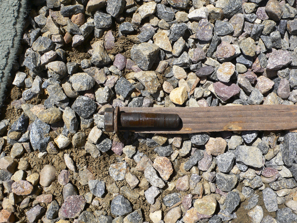
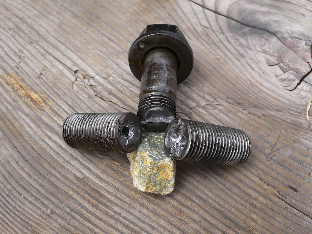
One of the bolts that came out from the bottom of the transmission mount was bent. If you look carefully, you can see the bend. These are metric 16mm 12.9 hardened bolts.
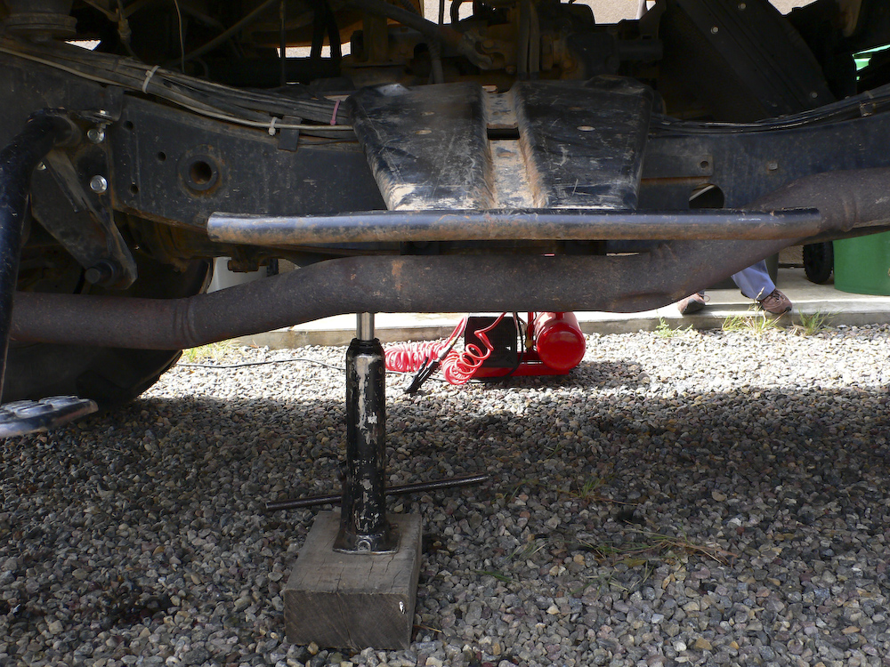
The transmission was jacked up to allow drilling into the bolt stubs to insert an easy-out screw extractor.
Note the quality weld.
The first 2 bolts came out easy. Basically, Kai drilled into them with a left hand bit and they just spun out. The last bolt, however, was another story.
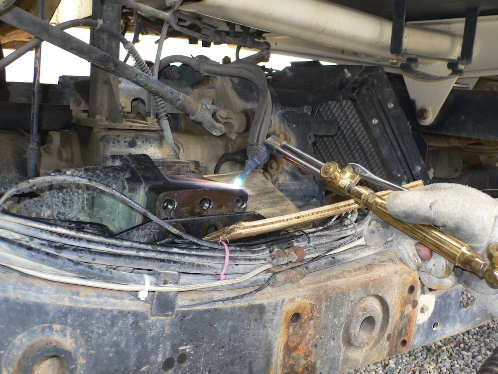
Try number 1. This fellow is tightly in there and will not come out. Kai thinks that applying the torch to heat the casing may break the hold that the rust has on the bolt fragment. We turned the easy-out so hard that we were fearful of breaking it, so we turned to the torch.
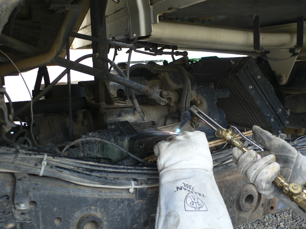
Try number 2, no good. Heat it again, apply mucho penetrating lubricant and hit it with the air hammer.
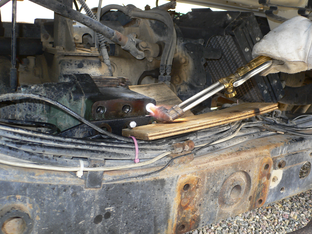
Still no good. Ok, no more Mr. Nice Guy. Now Kai gets fully medieval on that bolt. It did come out after this treatment. But there was much drilling, pounding and cussing involved in getting this bolt out. I am glad that I did not attempt this in the parking lot of the True Value Hardware in Page, AZ as I would have surely failed. Plus, getting the correct bolt would turn out to be an issue, taking a special order and several days for delivery.
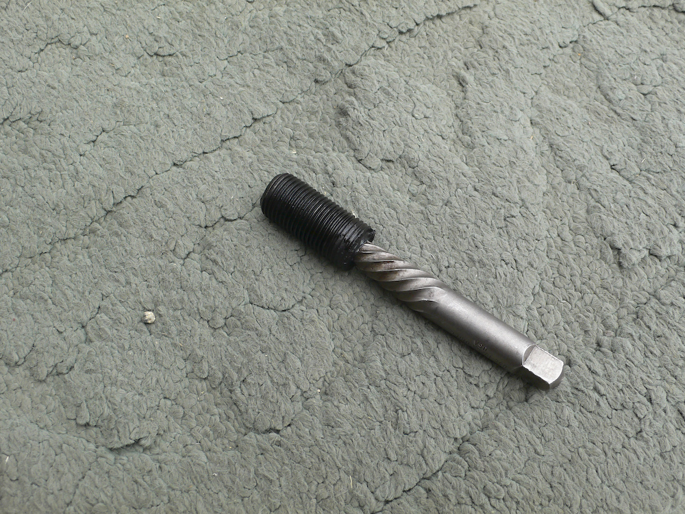
A souvenir.
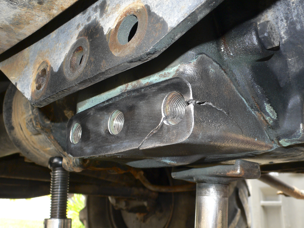
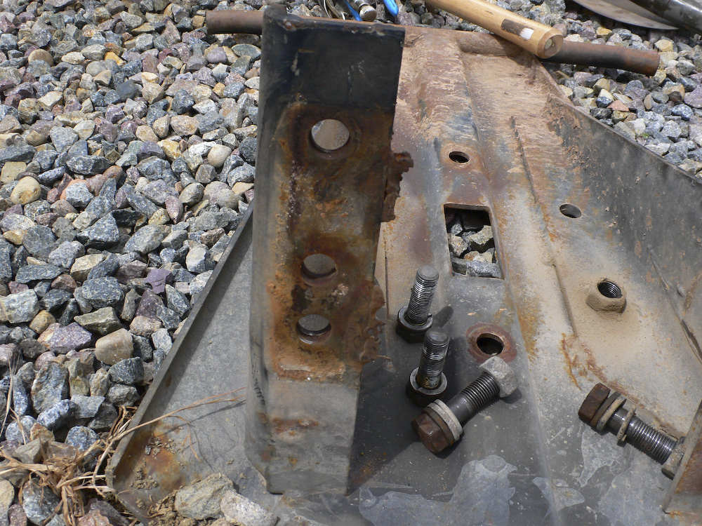
So, here is the bad news. This is a big crack. And, even if we could weld it, it would likely never handle the stress that is required. Some other alternative will be required.
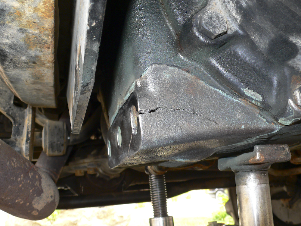
The crack is both big and deep. On closer inspection, it seems that the crack has been there for some time and may have started separate to this event. Clearly, this did not make it any better. The bolt hole in this corner of the case, is, in my opinion, not salvageable, thus requiring another approach. A number of methods of splinting the case were discussed, and in the end, all but one was discarded.
I had managed to connect with Mark Mitchell and we had worked out a date to start the effort to finalize the design of the splint. First, I visited him and we discussed in detail the plan and all the possible considerations. Then, we planned the work. The following day, we started in earnest. The photos below were shot during the design, fabrication and installation of the splint.
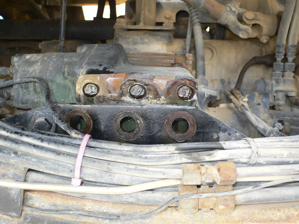
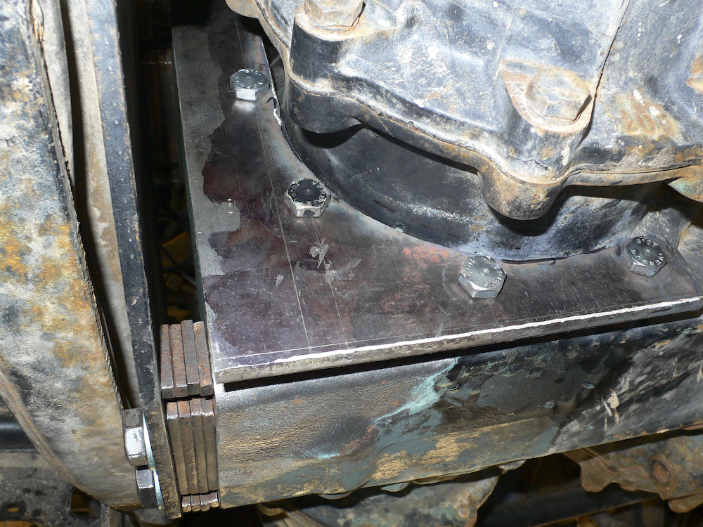
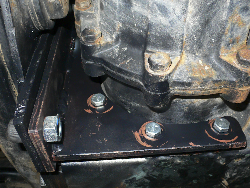
The plan was to make a crescent-shaped bracket and have that bracket bolt onto the aft torque tube housing. These bolts are seen on the right of the photo, with 3 bolts visible. These are M10x40mm class 10.9 bolts with hex heads.
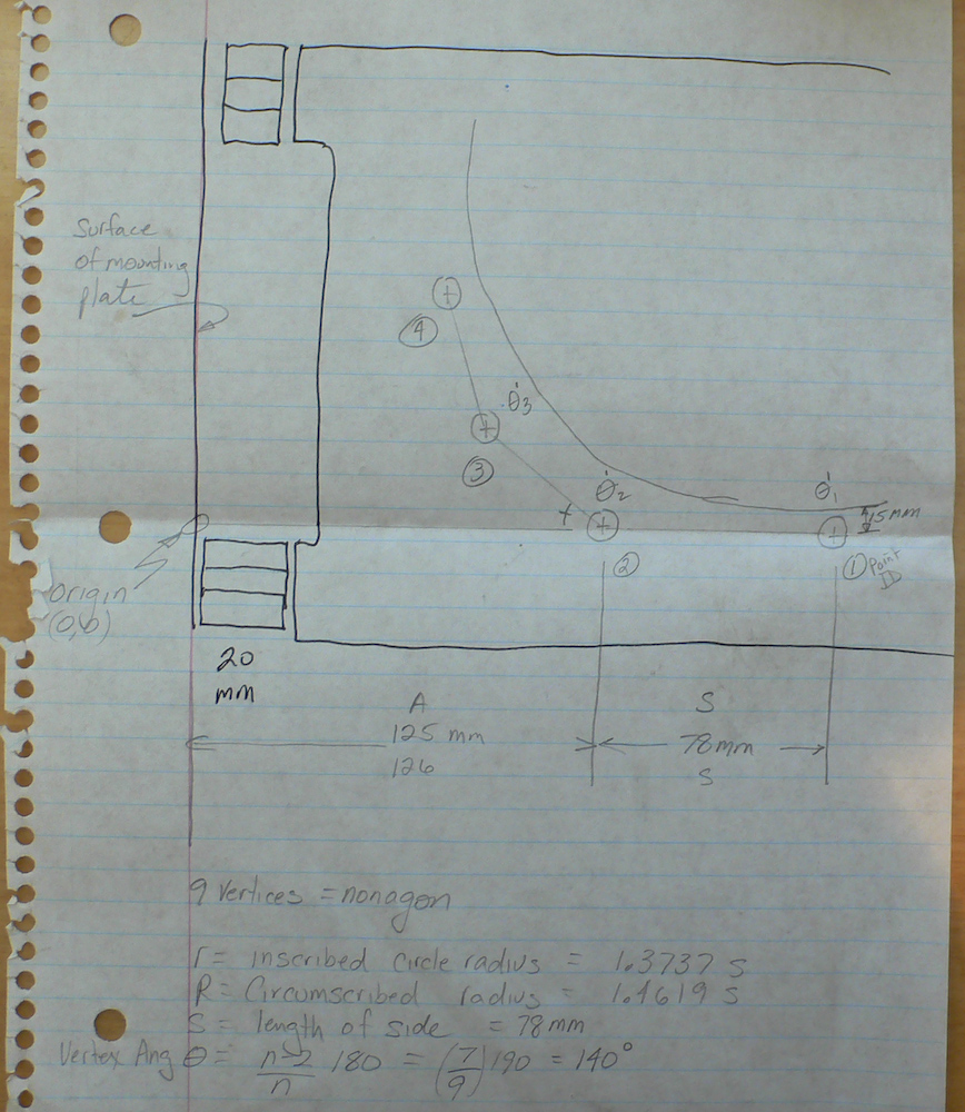
Here is a side view of the notebook page on the layout. Sadly, the case was a 9 bolt pattern which required me to exhume my CRC Math Tables to get the formula for a 9-sided regular polygon (called a nonagon). Once you assume the orientation of 2 of the holes, which in this case were horizontal, then the balance of the geometry is solely determined by the length of a side. So, making that measurement would be critical to making the bracket without having to ream and re-ream the holes. For the splint to be effective, it will have to be tight against the housing and to have all the bracket bolts tight with little or no play to accommodate the shear load due to the missing mounting bolt. Since the housing was cracked, I elected to not use the hole at all. The only real consideration was insuring that the combined strength of the 4 bolts is equal or more than the strength of the missing bolt. We were lucky that it was. Metric bolts are tagged with "classes" on the head of the bolt, in this case class 10.9. This class corresponds to the strength of the bolt. More specifically, it lists the failure strength and the point at which the bolt starts to stretch. These values are encoded in the head stamp. Class 10.9 means 100 N/mm^2 stress to failure point with a stretch point of 90% of the failure value. So, since the strength is expressed in units of force per area, if we know the area, then we can assess the overall force at the time the bolt fails. The strength of the missing 16mm bolt is PI* (16/2)^2, the old pi-R-squared formula, times the class number 12. In this case, the value is 2411 Newtons. For 4 bolts of the splint, the value is 3141 Newtons: score!
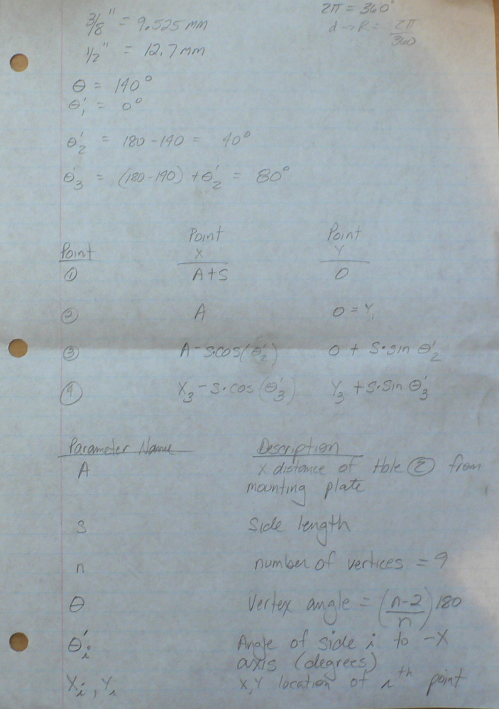
This whole thing was a good news, bad news. The good news was that the equations that determine the hole locations are easy to compute. The bad news is that the final results are critically dependent on the correct measurement of the inter-hole spacing (length of a side). Measuring accurately upside down is just plain hard. I had expected this and created a spread sheet that would allow me to enter parameters easily and then it would tell me the final locations. That was good, because our initial measurements were quite inaccurate, resulting in the need re-measure many times. The old adage: "Measure twice; cut once" was really "Measure 20 times, layout once".
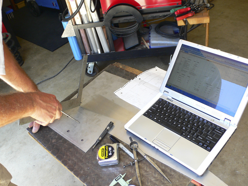
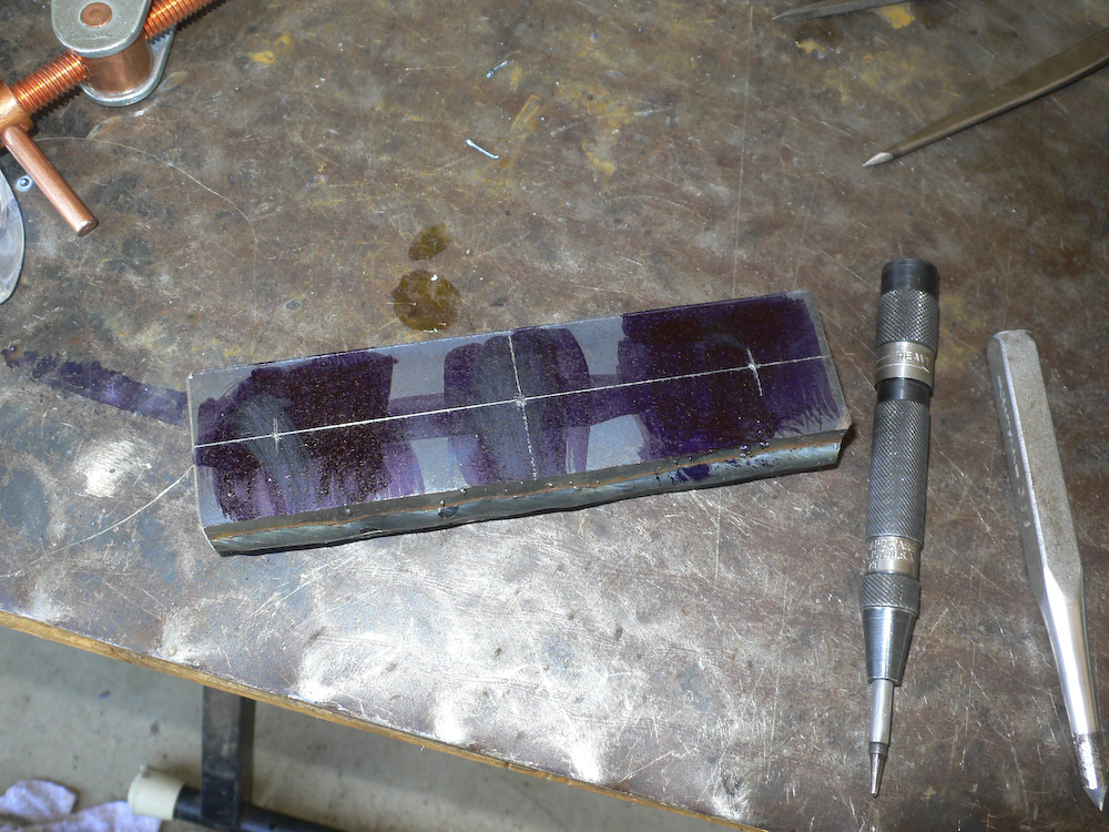
We used our initial measurements to layout the bolt hole locations in some scrap aluminum that we would use as a template. But, the holes we drilled did not come out round, so our estimates were not that good. The work piece had shifted during the drilling process.
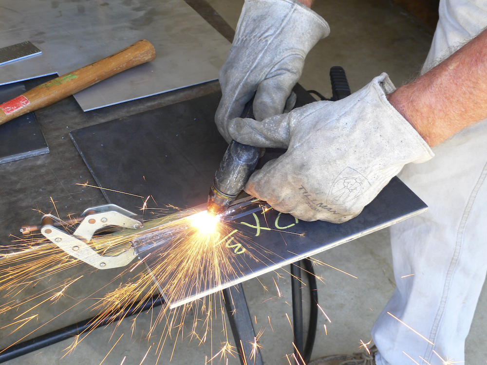
I removed the main bolts and Mark cut some plate with his plasma torch.
The holes are empty now, you can see where the plate will go.
The template went in well, but since the holes were not round, we had no confidence in the actual location of the bolts. In the end, we decided to re-layout the holes on the actual steel plate from scratch and ignore the template. The fact that it fit was a necessary condition, but not a sufficient condition for our success. In the end, this turned out to be a good decision.
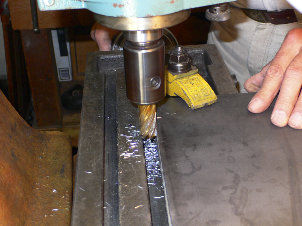
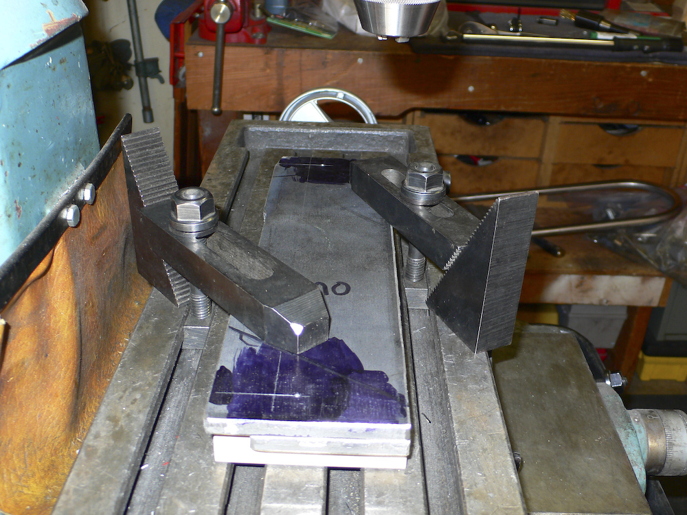
To get accurate locations, you have to have an edge that is straight. Here, Mark mill the edge of the plate to get a flat, straight side for the layout of the holes.
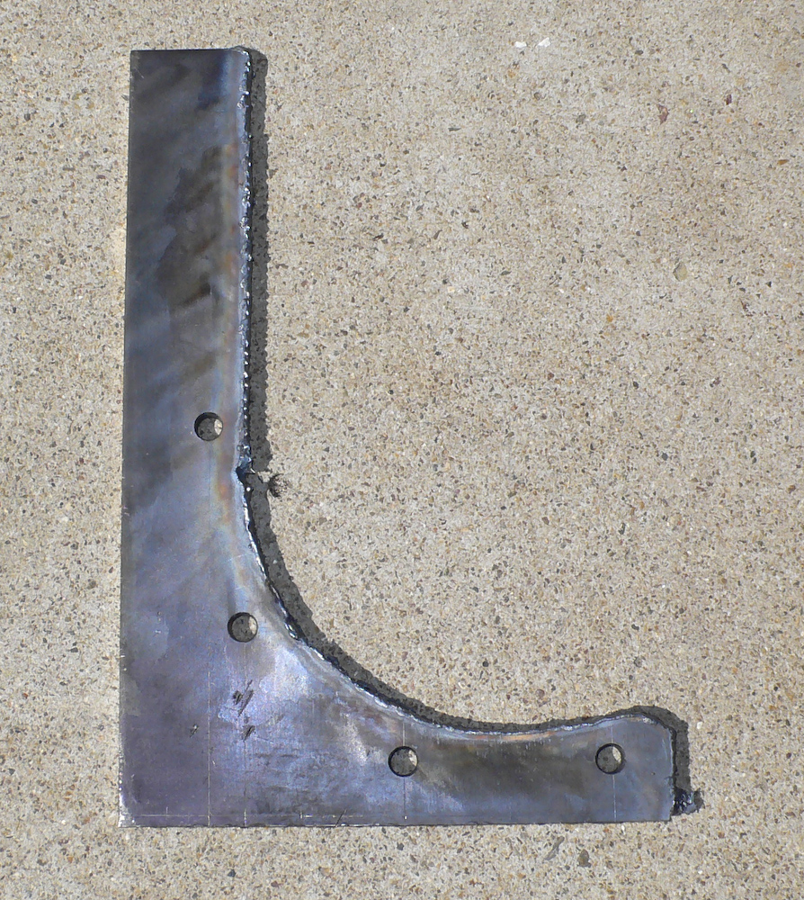
The layout went well and the next step was to drill the holes and then mark the curved surface. Once the curve was marked, I took Mark's cutting torch and cut the metal. Except for when the hose got caught on something and then jerked when it broke free, (thus the big hole about 1/2 way up), the cut went well.
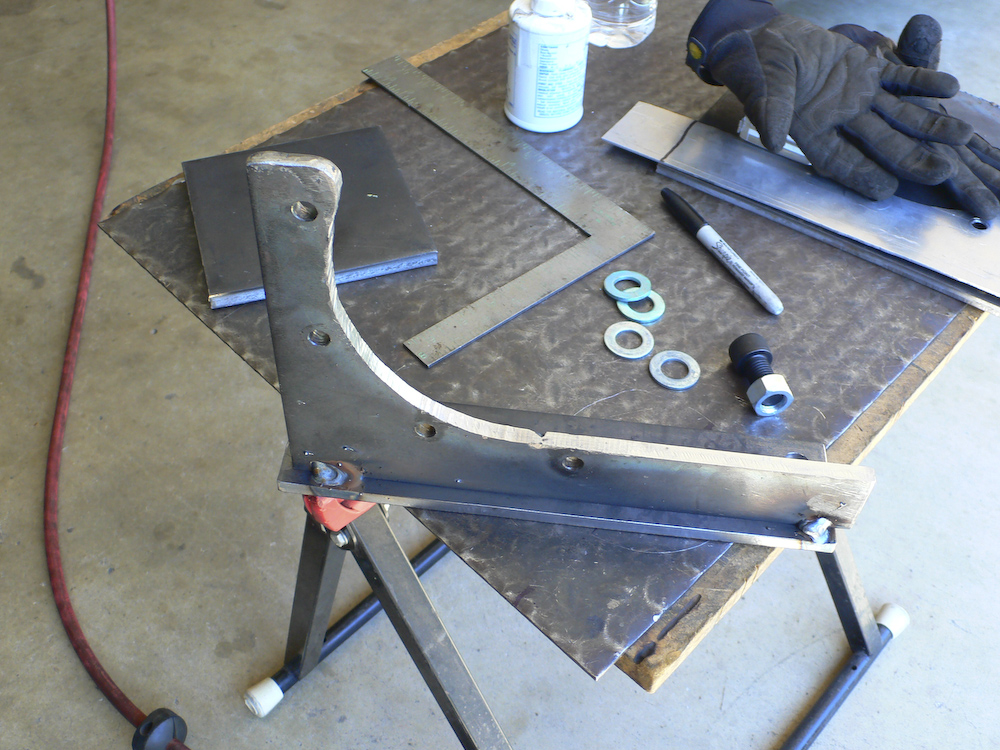
Yowzir. We hit this first time with no reaming required. We did find, however, that the inside curve needed to be radiused a bit as it was hitting the fillet on the casting. To do this, Mark put it in the mill and guided the curve by hand. Once re-installed, it fit like a glove. And the edge of the bracket was parallel to the mounting plate on the frame. The old shim stack is visible at the lower left of the photo. As a side note, due to the extra thickness of the bracket, I had to get longer bolts as well. These bolts JUST fit between the limits of the existing casting. But, to perform the installation, the bolts have to be inserted into the bracket before the bracket is moved into position -- otherwise, it will not fit.
Now on to the mounting plate and flange. These parts needed to share 2 holes in common and it was critical that they were perfectly aligned. So, the parts were clamped in the mill and gang-drilled.
Crescent plate was then welded to the flange.
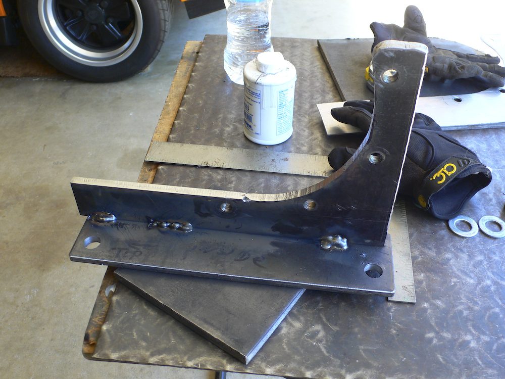
The tacks were complete, then the frame was hard-welded together.
Mark mounted the other plate onto the frame and welded it tight with his MIG welder. Then the assembly was sprayed with some paint.
Two half inch plates were welded together into a stack to make the 20mm shim block that will replace the stack of shims that have been on the truck since I bought it 12 years ago. The hole positions were laid out and the holes were drilled. Then, the stack was cut to a thickness of 20 mm with the mill.
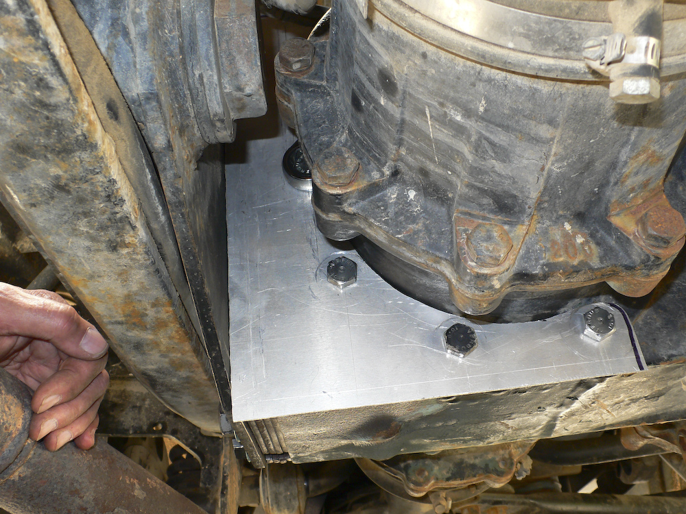
This could not have come out any snugger. There was a very small warp of the angle of the flange with the bracket, but it did not impact the ability to assemble the unit. The old shim stack is visible at the lower left of the photo.
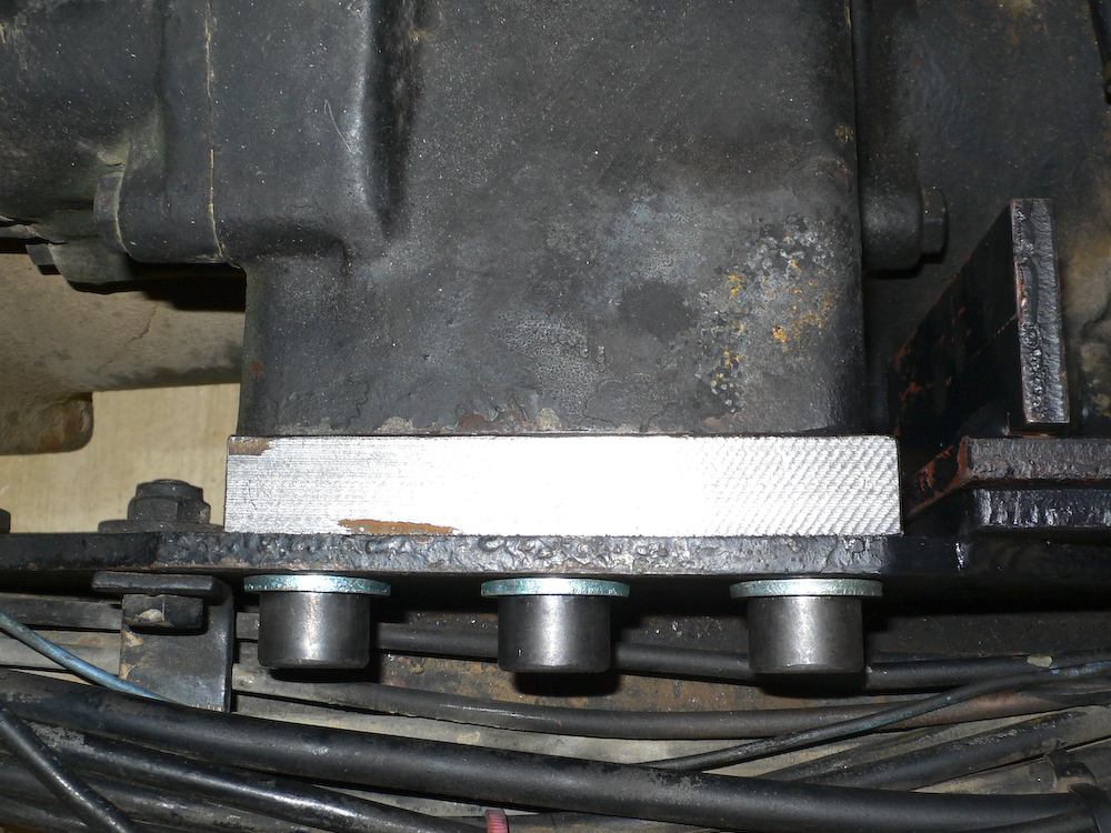
The last act was to replace the wimpy 8.8 bolts with factory-spec 12.9 socket head cap screws and insert the shim blocks. This was a tight fit, but it did not require reaming the holes - they were correct as measured and drilled. The shim block is the silver part. The splint is visible in the lower right of the photo.
The final view, fully assembled and ready to drive.
This went surprisingly well. Usually, you can never measure very accurately, and measuring upside down on a curve would be hopeless for me. Special thanks to Kai and Mark for their assistance, without which this would not have been possible. The only item remaining is to drain and replace the tranny fluid for inspection and to insure that any metal fragments from abuse during the failure are removed.