Slide Out and Tool
Box Repairs
Addressing
a "Dumb-damental" Design Flaw in Our Lance Slide Out
Event Report
20230720
Back to Bill Caid's Home Page
Background
We purchased our Lance
pull-trailer back in late 2018 and performed our build-out in
2019. Since then, we have logged well over 20K miles on
and off the road with this setup. During this time, we
have been reasonably careful about treating the slide out with
respect. To be honest, it provides a ton of additional
room within the living quarters and is relatively easy to deploy
and retract. Of course, all benefits of the mechanism are
nullified when a failure happens. Our worst-case scenario
was that the mechanism failed with the slide out extended thus
preventing us from driving. A failure when retracted,
while annoying, would only be that - annoying. Most of the
interal systems can operate with the slide out retracted.
Indeed, we have slept in the living quarters for weeks on end
during the build-out with the slide retracted. It was
annoying, but functional.
During our last outing
at the end of COVID, we noticed a separation occurring between
the mounting flange and the outside skin of the Lance.
Several of the flange mounting screws were broken due to
stresses. Since we had been off-roading, I simply assumed
it was stresses associated with torsion on the Lance.
Future travels and extra information would prove that was not
the case.
Turns out that this
problem has been reported by a large number of Lance owners, at
least those that actually use their campers. And, this
problem has been known by the vendor for some years. In
fact, the vendor has an approved "repair" for the issue, but the
repair does not address the root problem. The root problem
is simply too much unsupported mass on an extended moment
arm. That mass and the lever action ("moment" in
engineering terms) resulting from dynamic loading from bumps in
the highway causes the mounting flange to tear away from the
outside skin. Given enough road forces, the separation
would continue and would render the slide out useless.
The Solution
Basic engineering is a
wonderful thing. Certain laws apply, and when you attempt to
violate those laws, you get "corrected" in short
order. In this case, having a substantial mass on the end of
a long moment arm (the slide out enclosure) and subjecting it to
dynamic loading (a
heaving bump in the interstate) results in huge
forces. The "correction" in this case was separation of the
mounting flange from the outside skin of the camper.
Reattaching the flange to the skin, while simple, does not result
in a true fix as the root problem (the unsupported, cantilevered
mass of the slide out) remains unaddressed. So, providing
support for the cantilevered mass while in motion IS
the actual fix. Although in this case, other actions were
required for either completeness or ease of use.
In addition to the factory-specified repair actions, we utilized
two approaches to address this issue. The first approach
sought to minimize further damage and the second approach sought
to minimize the setup and teardown hassle.
The photos below are
what we saw.
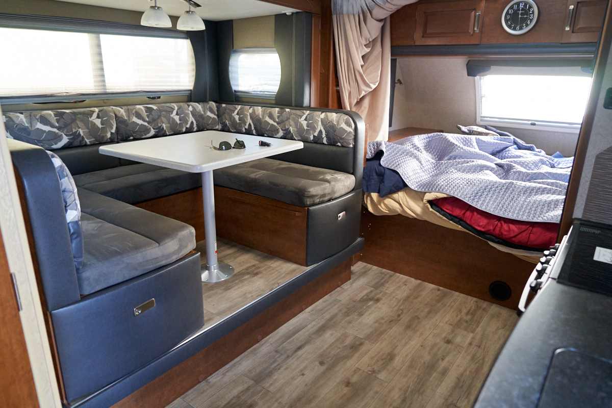
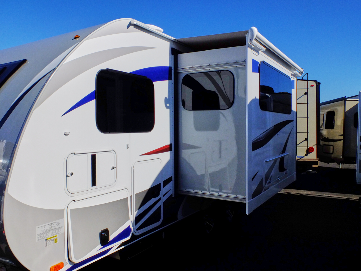
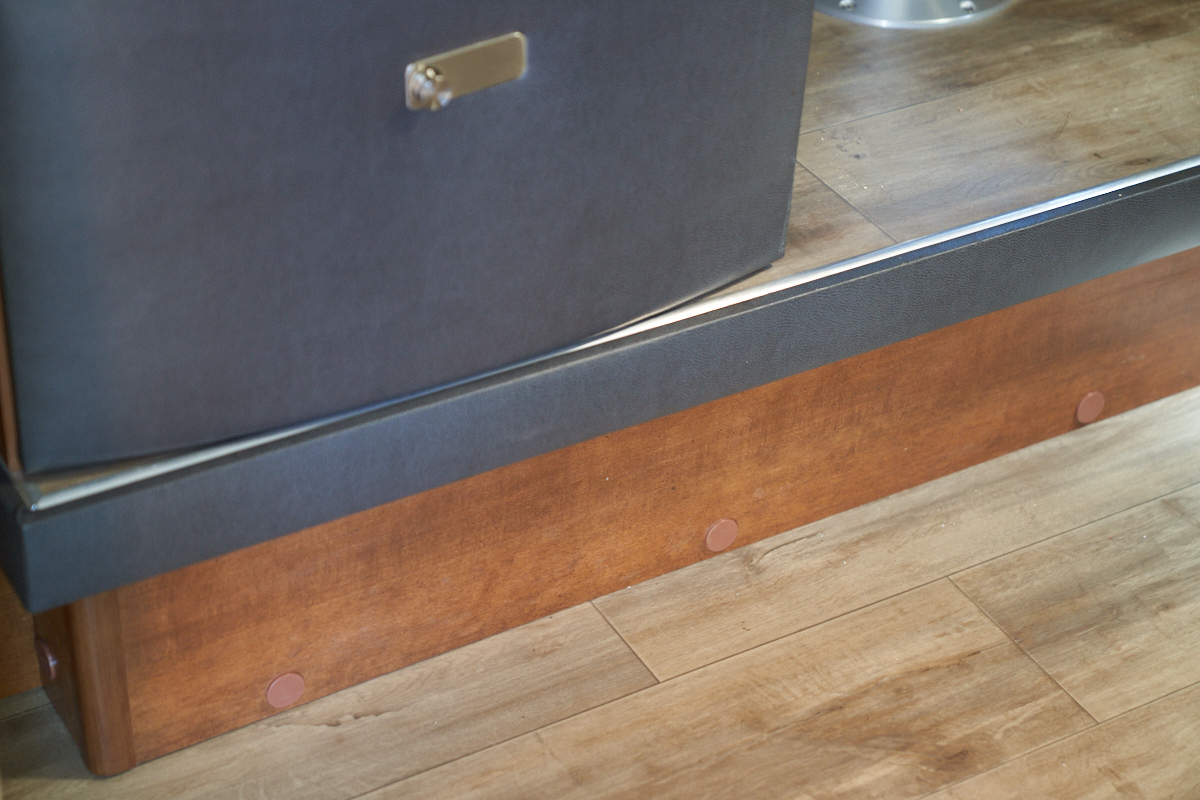
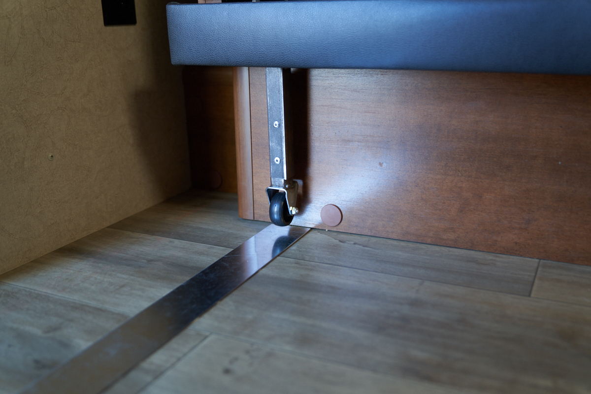
This photo was taken while the Lance 1685 was still a
pull-trailer. Note the room available due to the
slideout. When the slide out is retracted, the padded
facia is about where the black vent is under the bed.
When viewed from the outside, you can see the upper and lower
gear racks that are used as part of the activation
process. Inside the wall is a motor and 2 gears on a
common shaft. The top gear engages the top rack and the
bottom gear the bottom rack. They are on a common shaft to
prevent sagging of the slide out when extended.
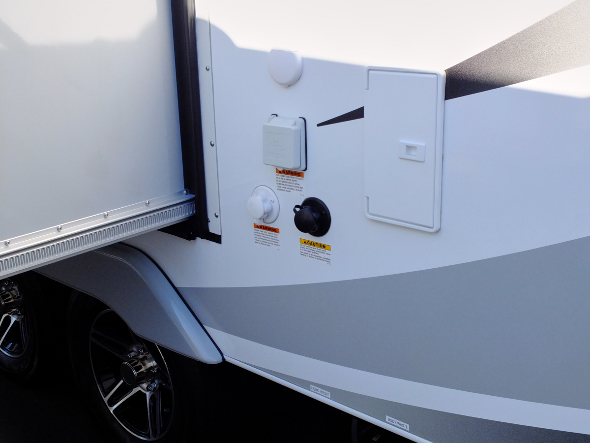
A closer view of the bottom gear rack. Note the white
flange on the wall of the camper. This flange is being
torn from the wall by the unsupported weight of the slide out
when retracted.
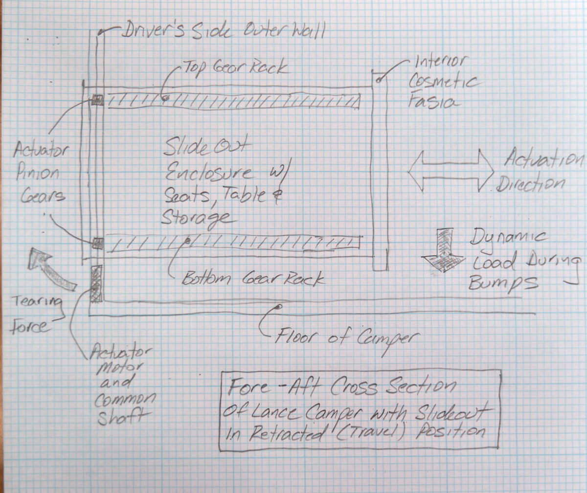
A drawing makes better sense of the forces applied to the
various components. The slide out is only supported by the
gears, racks and common shafts of the actuator assembly.
There is a front and rear motor and they are synchronized
(somehow) to keep the slide out from jamming. When a
dynamic load is applied, say with a heaving bump in the freeway,
the load is turned into a tearing torque that manifests on the
lower-outer mounting flange.
On our extended road trip, we met a couple at the Montrose KOA
that also had a Lance 1685 but in the factory pull-trailer
configuration. They, too, had the flange separation
problem and discovered that there was a factory approved repair
for the problem. He described the repair in detail and I
realized that the fix was only a partial fix. The real fix
was to prevent the problem from happening in the first place by
eliminating the unsupported, cantilevered weight of the slide
out using some kind of adjustable support. In Colorado
Springs, we purchased 2 4-ton hydraulic bottle jacks from Harbor
Freight. We used them to get us across the Rocky Mountains
and to Durango, CO. But, we had noted that the jacks would
sometimes slip into a location other than the starting position
due to the dynamic forces encountered during a big bounce.
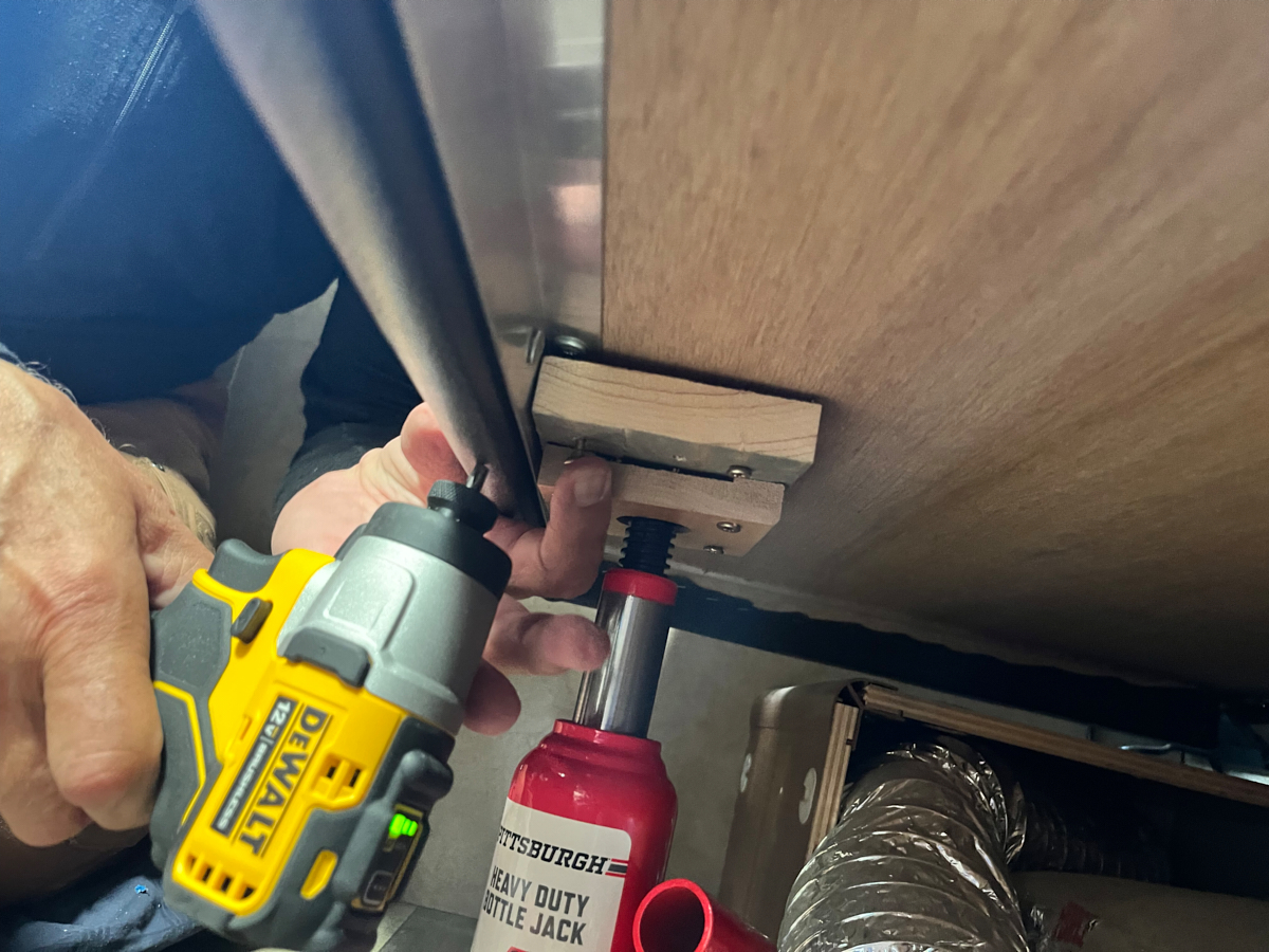
So, when we reached Durango my friend Brad assisted us in
fabricating a mechanism to "trap" the jack in a known
location. For each jack (one fore and one aft) we cut 2
wooden blocks. One of the blocks had a hole drilled to
accommodate the load end of the jack to provide the trap.
This block was then screwed into the other block to assist in
spreading the load of the jack so it would not punch through the
underside of the slide out. In the photo above, you can
see the pair of blocks on the aft side of the slide out.
Since Brad did not have a full set of wood working tools (in
this case a router), the block was not flush with the surface
due to the thickness of the aluminum angle. It looks ugly,
but works well. The bad news is that you must position and
raise both jacks to the correct height upon retracting the slide
out. And, more importantly, you must lower and remove the
jacks before attempting to extend the slide out. A
workable solution, but at the cost of added inconvenience with
each cycle of the slide out assembly. A different solution
is needed to make the fix both convenient and robust.
We started measuring sag
on the walls and determined that we were seeing 2.5" of
drooping before installing the factory-approved repair
action. After the repair, the droop was down to about
0.5 inch, but the weight of the slide out and the contents of
the clothing drawers was still unsupported and
cantilevered. This meant that the repair, too, would
fail if subjected to sufficient dynamic loading. We
devised an improved plan that called for leaving the current
jack cups in place in case we needed them again and augmenting
them with a set of caster wheels that would support the
cantilevered weight over the entire range of motion of the
slide out actuation. We had noticed that the sound of
the slide out extending and retracting greatly degraded with
the amount of droop (the motor had to work much harder with
the odd torsional forces on the slide out). Implementing
the factory fix made the motor sound better and the rate of
motion became substantially faster.
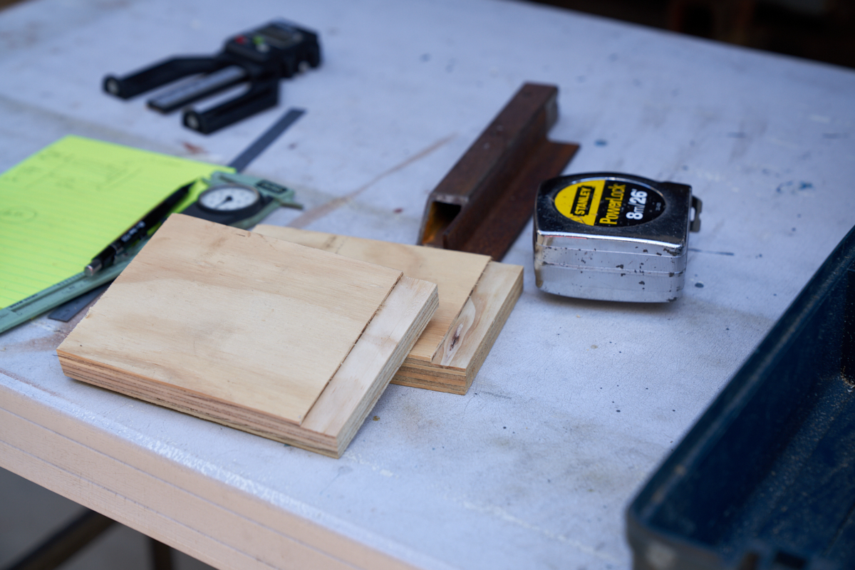
The caster wheels would need to be on a column and the column
would need to be securely fasted to the slide out. So,
the first task was to get a flush-mounted support
fabricated. Measuring the thickness of the aluminum
angle told us how much material needed to be removed to
provide the flush mount. In the photo above, the first
routing pass has been made on the left side of the board
clamped to the work bench.
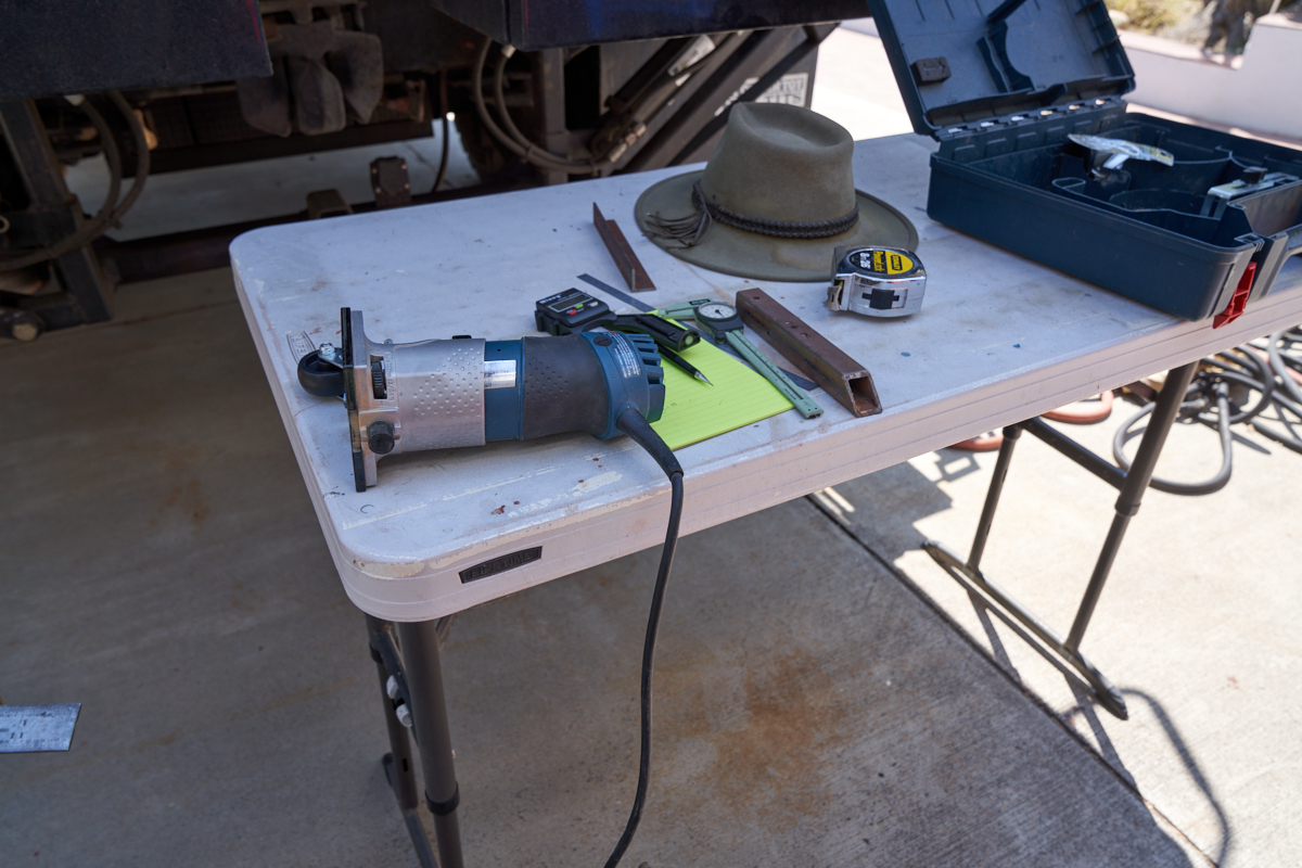
I used my Bosch hand router with a square bit to remove the 0.1"
of material needed.
Once the mounting plates were routed, they were cut to length.
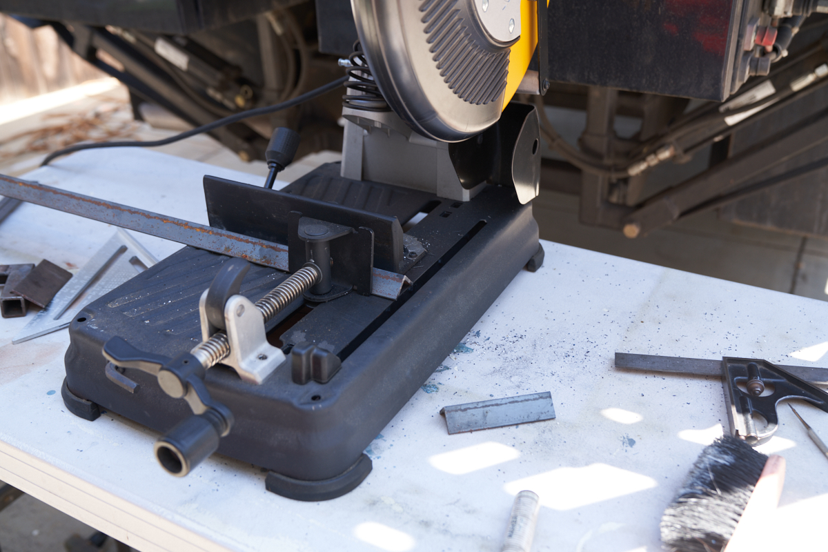
Next, some 1x1" angle needed to be cut to fabricate the
column. My cold cut saw did the job nicely.
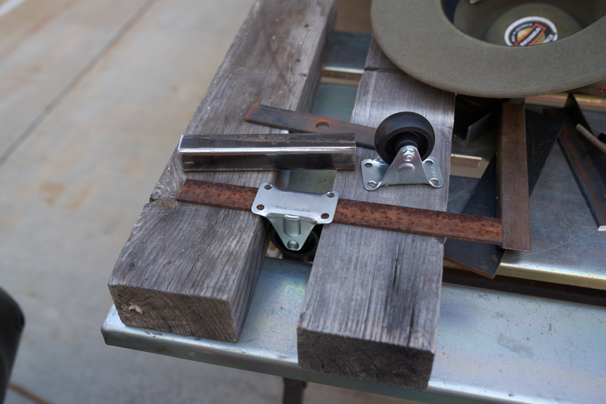
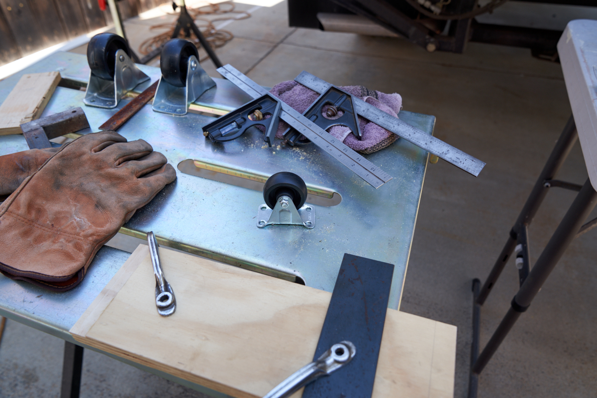
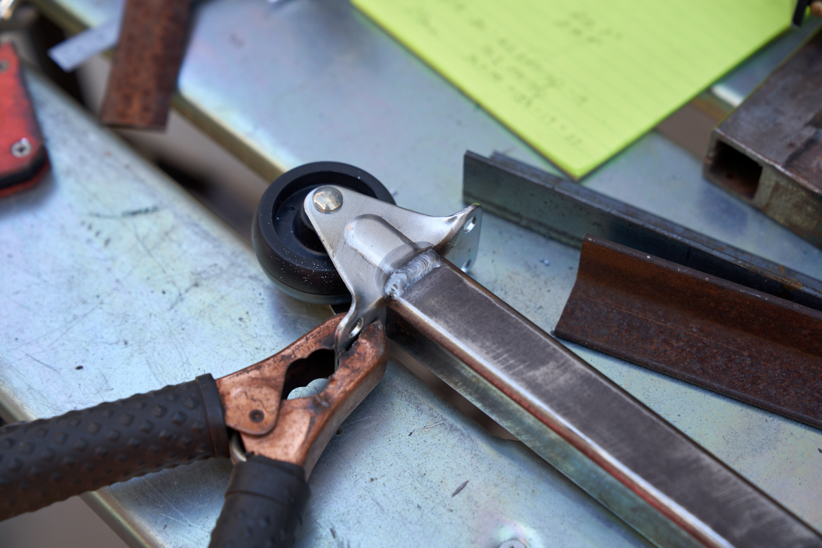
The caster wheel assembly would be welded to a 7" length of 1x1"
thick wall square tubing. The trick was to get it "jigged"
correctly so that the wheel was correctly aligned with the axis
of the tubing. The plan was to drill a hole in the center
of the wheel mount to allow insertion of a threaded rod.
Above, the wheel is test-fit onto a strip prior to drilling.
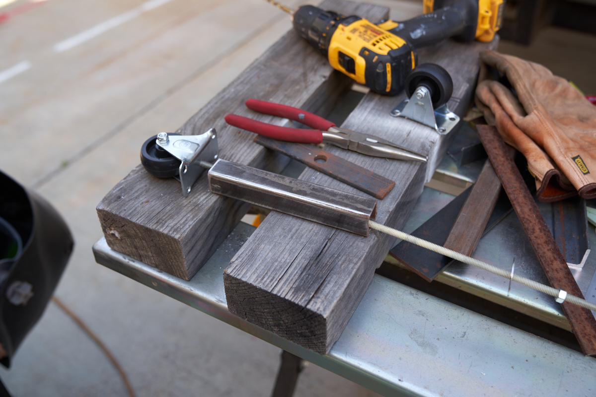
Once the hole was drilled in the center of the mount, the rod
and a nut was added, then the tubing, then a fender washer and
another nut.
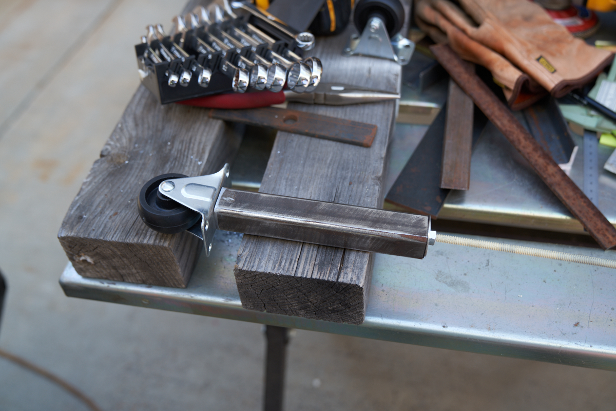
The whole assembly was positioned, aligned and the nut was
tightened on the rod to hold the assembly securely.
My MIG welder was used to run a bead between the wheel mount and
the tubing. A bead was run on the opposite side as well,
then the threaded rod, washers and nuts were removed.
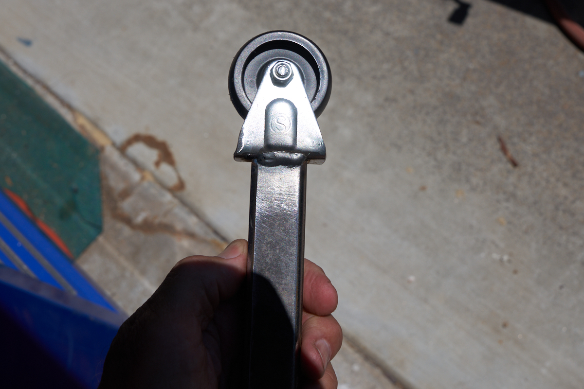
A cutoff wheel was then used to remove the unneeded overhanging
portions of the wheel mount to provide better clearance from the
toe kick plate when installed.
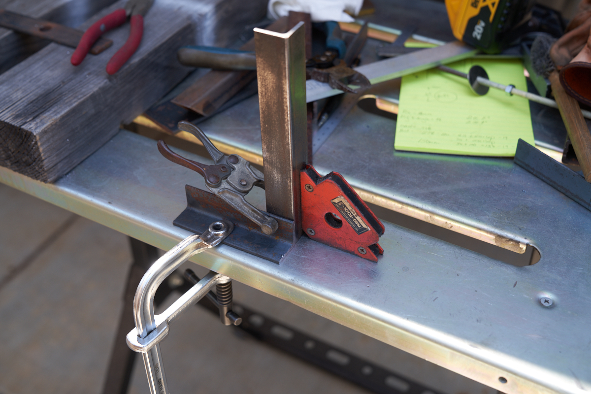
The pieces of the 1x1 angle legs were jigged and clamped in
anticipation of welding.
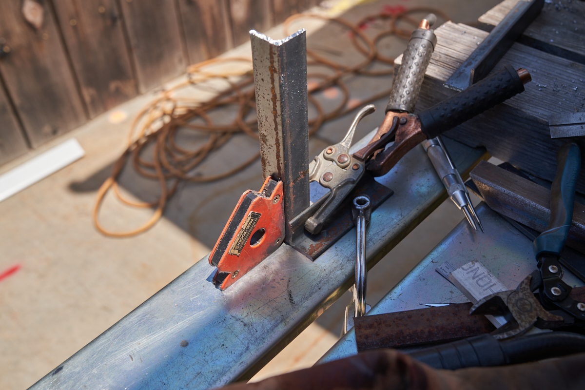
The legs were assembled as mirror images (one left, one right)
so the open portion of the angle was toward the center of the
slide out to provide better access for final assembly.
Once welded, holes were drilled in the mounting flange (short
leg) to allow attachment to the bottom of the slide out.
The legs were attached to the mounting plates using 1/4 x 1" lag
bolts.
Recall that under the center of the cargo drawer is the wooden
pocket for the hydraulic jack. The mounts for the legs
will be installed to the outboard side of the pocket.
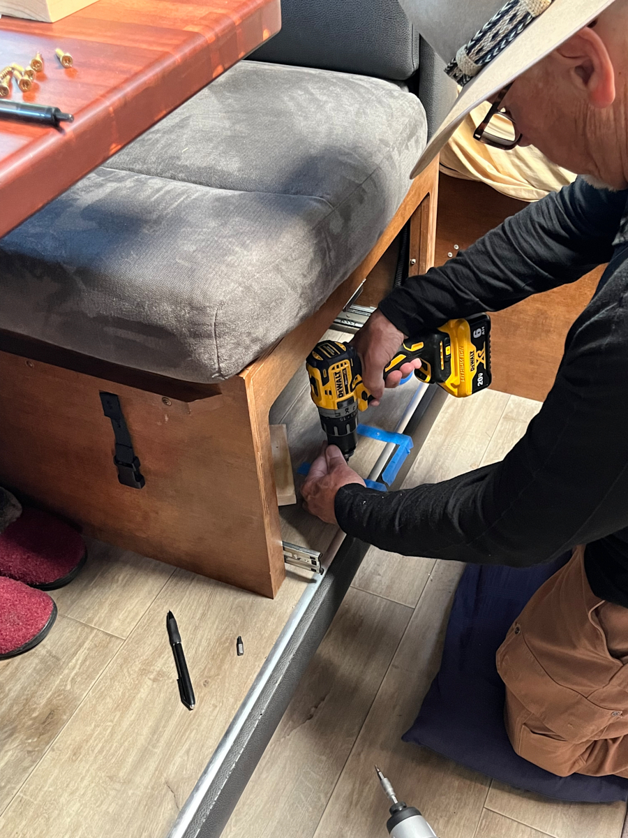
Locations of the through-holes were marked on blue tape and were
drilled for insertion of 1/4-20 x 2.5" stainless steel bolts.
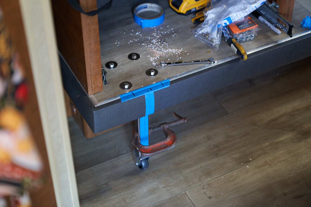
Bolts with large fender washers were inserted through the holes
and the mounting plates with legs were attached and secured with
Nylock nuts. Once the legs were attached, the tube/caster
assemblies were added and clamped in place as a height
test. This method was used to address two critical issues:
1) ability to assemble in-situ; 2) to allow last minute
adjustments in height based on the observed sag of the slide
out.
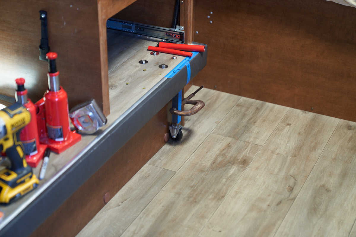
The other side was installed, wheel height set and the slide was
actuated to test its behavior. Setting the height using
the fully retracted position of the slide out as the baseline
produced an excessively tight fit. So tight, in fact, that
when the slide out was retracted, the point loading of the
caster wheels depressed a groove into the flooring
material. Sadly, the U.S. RV industry uses the cheapest
possible components. In this case, the floor is a sandwich
of 1.5" Styrofoam panel glued to 2-1/8" thin plywood cover
panels. This configuration, while lightweight and cheap,
is not robust to extreme point loads produced by the caster
wheel when supporting several hundred pounds of cantilevered
slide out. The Styrofoam directly under the center of the
wheel track was crushed by the load. After an extensive
conversation, we concluded several things. First, the load
on the wheel will be determined by what slide out location is
used to set the baseline wheel height. Second, application
of a stiff strip of metal would spread the load and prevent
damage to the flooring material, albeit at a "visual cost" to
the result.
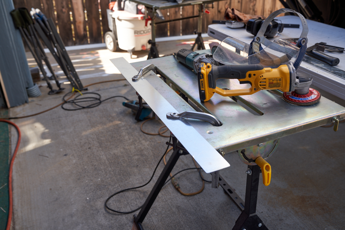
A trip to the "steel store" (also known as Industrial Metal
Supply) got me a 12x48" strip of 16ga (0.05") galvanized sheet
metal. The sheet metal was cut with my worm-drive saw with
carbide steel blade and the resulting strips were de-burred and
dressed.
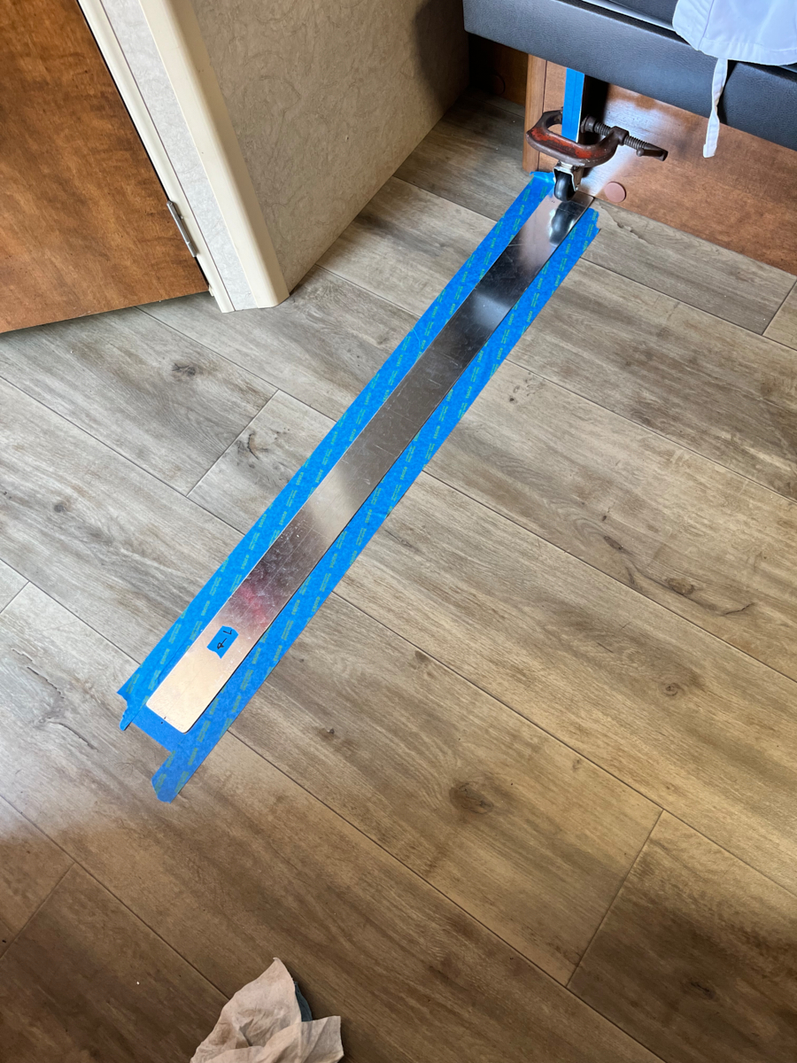
The clamps were released and the wheel removed. The 16ga
strip was positioned on the floor and the location was marked
with blue tape. Both the floor vinyl and the sheet metal
strip were thoroughly cleaned with a damp cloth followed by
acetone to remove dirt and grease to insure good adhesion with
the glue.
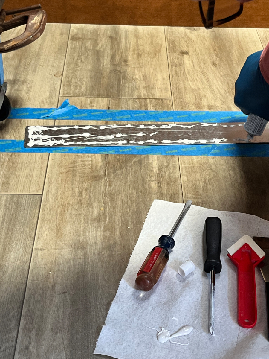
Small amounts of 3M 5200 adhesive/sealant was used to attach the
load spreading strips to the vinyl floor. Blue masking
tape and weights were used to hold the strip in place while the
adhesive cured.
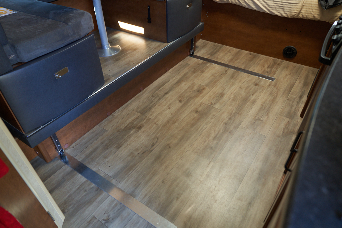
The strips were installed, weights applied, excess glue
was removed and we waited for a 48 hour curing period before
additional testing. In the photo above the strips have
been installed, glue cured and blue tape removed.
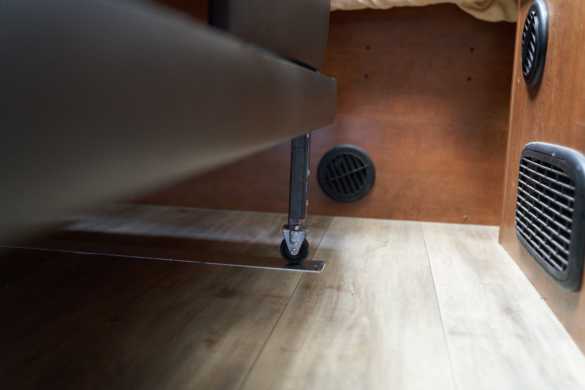
We used the height of the slide out at the 1/2 extended position
as the baseline for setting the wheel heights. With
this baseline, the wheel is not in contact with the plate for
over half the travel distance, demonstrating the variance of the
height due to sagging. Note that the wheel is elevated
above the support strip while the slide out is fully
extended. Note that the position of the tube in the leg
frame must be evened out over the extremities of slide out
motion. In the photo above, the vertical position of the
tube has been selected, and 2-3/16" holes were drilled through
the leg and tube and an aluminum pop rivets were installed
setting the height of the wheel. Note the height of the
wheel above the rolling surface when extended.
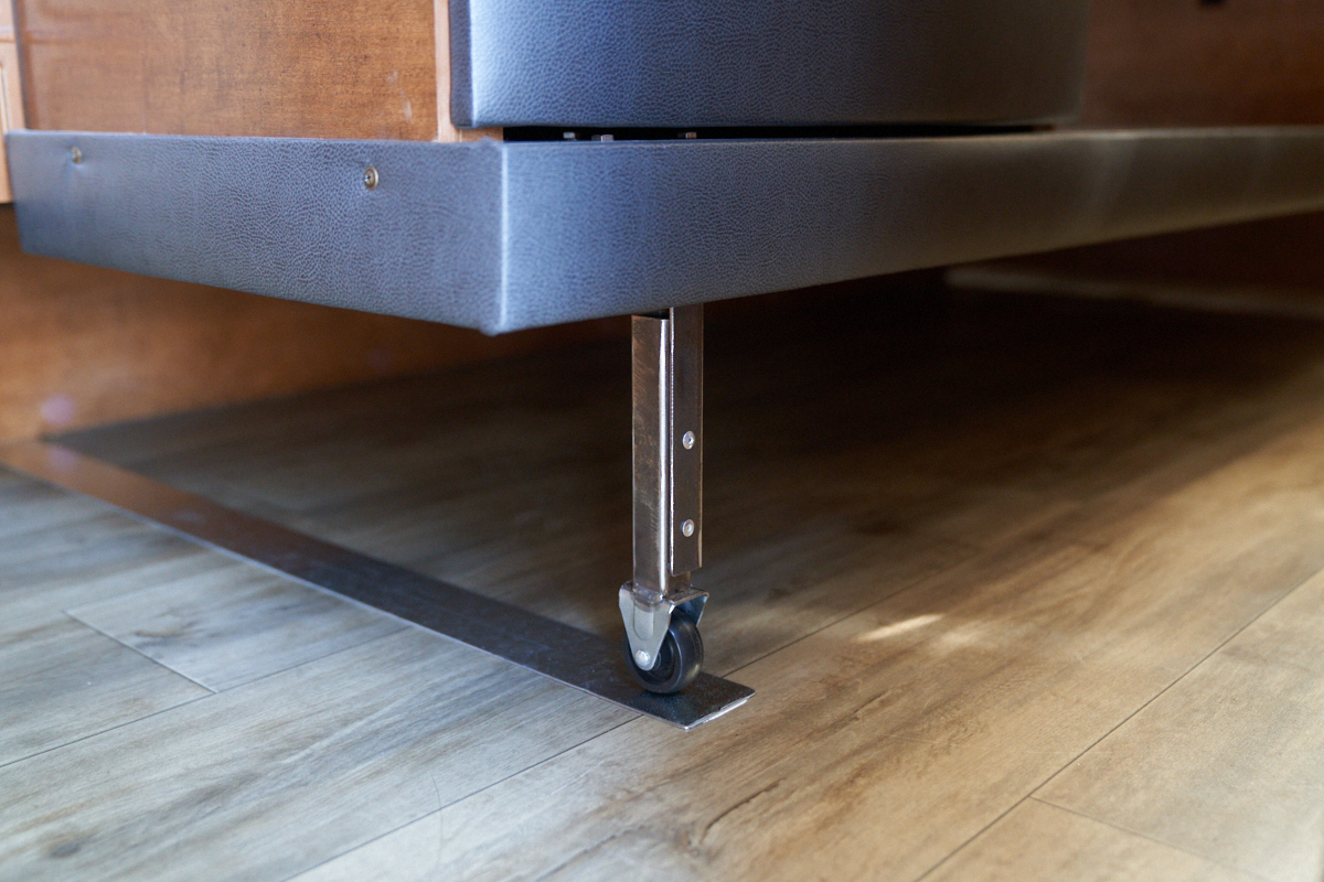
The forward leg showed similar height properties to the aft leg,
showing that the variance in height was common to both
sides. In the photo above, the slide out is in the fully
extended position.
We selected the center
of the slide out in-out motion (half retracted) as the
baseline for wheel heights. The assumption was
that the mass would be effectively balanced at this position and
therefore the height would be "neutral". In this photo,
the wheel assembly is in full contact with the aft metal strip
and the slide out is in the fully retracted position.
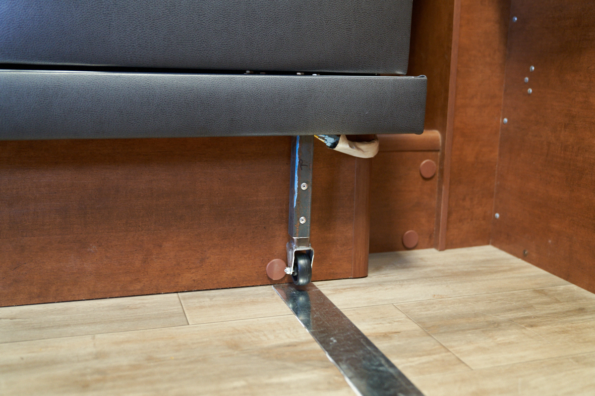
The forward wheel of the slide out in the fully retracted
position. It is true that the legs are a kicking/tripping
hazard, but forewarned is forearmed. We felt that the
severity of the hazard was worth the added convenience of easy
extension/retraction.
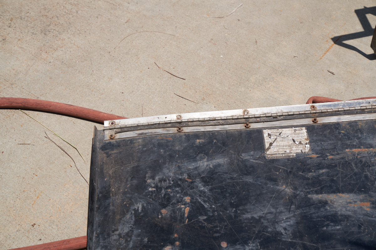
On to the next task: repairing the rear tool box hinge.
Thor has 3 large (24x24x36") steel tool boxes that are used to
carry "stuff". One carries large tools and pry bars, one
carries the folding stair assembly and lawn chairs and the last
one carries our electric unicycles (EUC). The aft driver
side box is the one that takes most of the hits because it is in
the least visible position. That box has been repeatedly
tagged over the years on large boulders and similar off-road
obstacles. The impacts have taken their toll on the hinges
and mating surfaces of the box to the point that a repair is
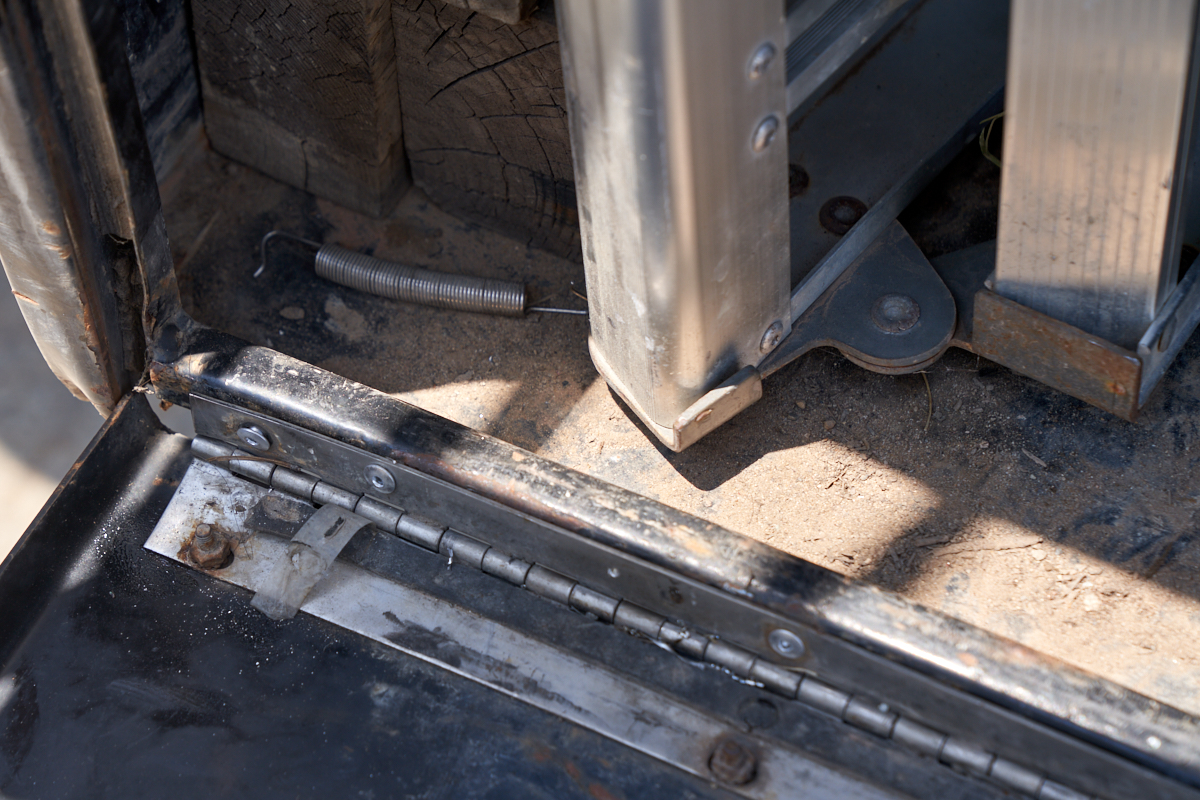
needed. To gain the necessary access for the repair, the
door must be removed. This required drilling out the pop
rivets used to attach the hinge to the box. Above, the
door is free, note the bend in piano hinge due to the impact
damage.
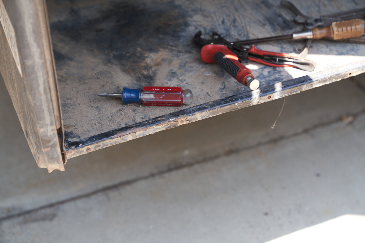
Once the door was removed, the main box was adjusted using a
Harbor Freight hydraulic "power pack" and some wooden
blocks. The blocks were placed between the ram of the
power pack and the sides of the box. The ram deformed the
box walls and straightened the mountain surface. Pry bars
(AKA a screwdriver) and vice grips were used to straighten the
mounting edge that had been crushed by the impacts. Note
the edge deformation on the lower left corner of the box.
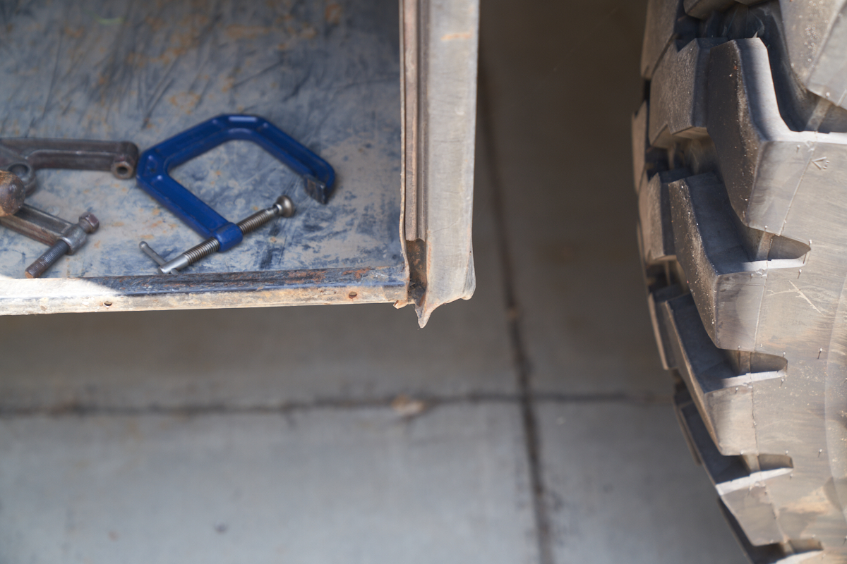
The leading edge of the box had taken some good impacts as well.
Once the mounting edge was straightened, the door was
re-attached using 3/16" pop rivets and rivet gun.
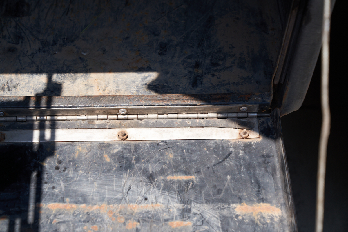
The aft corner of the door mount had suffered sufficient damage
to require an additional pop rivet to insure mechanical
integrity. Above, it can be seen that the rear-most rivet
did not set fully due to the deformation in the mounting
surface.
It remains to be seen
whether our wheel-based repair will stand up over the long
run. While it is easy to complain about poor designs or
cheap material choices, the fact is the basic Lance design would
work fine for most folks who use it in a "nominal
situation". Our usage scenario is far from nominal, so they
get a pass in this case. That said, it would have been nice
to have been told that this was an item of concern and had we
known that, we would have installed the wheels from the get-go and
the whole issue would have been prevented. For those folks
who are not lucky enough to have access to metal working tools and
a welder, the simple jack and pocket solution is a full solution
to the problem except for the wear-and-tear on the motor and gear
racks associated with the sagging.
I am still a Lance fan, but now I have some reservations.
And I am sure that the have reservations about me. And they
would surely have reservations about me slaughtering their product
and mounting it on Thor and subjecting it to a good thrashing
off-road. But the truth is than the biggest hits we suffered
were on-road. The reason is simple - when
off-road I alone control the motion of the truck and can therefore
choose how to navigate obstacles. But, when on the highway,
the flow of traffic controls where you drive (lane) and the
speed. Sometimes, discontinuities in the road bed are
unavoidable due to inability to change lanes in time or inability
to avoid the obstacle safely. So, in my mind, Lance should
come up with a conclusive solution for this issue and fold it into
the manufacturing process so all buyers benefit from the change.
Back to Bill Caid's Home Page
Copyright Bill Caid 2023. All rights
reserved.