Permanent Telescope
Mounting Pier Construction 2024
Implementing an easier and cheaper solution to the mounting
and pointing problem.
Event Report
2020418-22
Back to Bill Caid's Home Page
The Experience
I have been interested in
astrophotography for many years and over the years have
accumulated a set of tools to assist me. But, the one tool
that I never had was a permanent telescope mount. In the
run-up to the 2024 solar eclipse, I stumbled upon a much simpler
approach to building a pier than the typical poured concrete
pier. While I did not bookmark the source of the plan,
the crux was that the column was constructed of concrete block
rather than having to form and pour a column. During the
multi-day drive from San Diego to Illinois for viewing the eclipse
I further simplified the plan to remove the need for any concrete
mixing.
Any mount has to be 1) rigid and stable; and 2) level (i.e. the
upper surface has to be normal to the gravity vector). Any
concrete structure meets the first requirement, but meeting the
second is more challenging than one would expect especially since
"level" need to be within an arc-second or so of true level.
So, we devised a couple of tricks to make our life easier.
Most tracking mounts available today have some kind of metal
adapter that allows connection of the tracking head to the
pier. These adapters should be assumed to be brand/model
specific. We obtained a tracking head and its associated
pier adapter.
The photos below show the initial construction of the pier and the
subsequent completion with provisions for electrical service at
the pier for the drive motor. Should anyone be interested in
following this plan, the bill of materials is as follows:
- 2 standard cored
concrete blocks (sometimes called cinder blocks).
About $3 each.
- 1 sack 3/4"
crushed gravel. About $4.
- 1 pre-fabricated
concrete pier block (they come in sizes, we used the smaller
size because it is was a scrap block that we had on
hand, but I would use the bigger size if this action were
repeated). About $20.
- 1 tube good
quality multipurpose adhesive.
- 1 plastic shim
pack.
- 1 package wooden
grade stakes.
- 4 2x4s for
framing.
- 1 2 gang junction
box with weather cover.
- 1 90 degree
conduit angle
- N pieces of 3/4"
conduit to meet your wiring requirements.
We later decided to add a concrete skirt around the column to help
reduce the dust when using the mount. We framed and poured a
34" square skirt which used 6-60# sacks of Quickcrete
concrete. We also added some rebar "just because" to insure
structural rigidity.
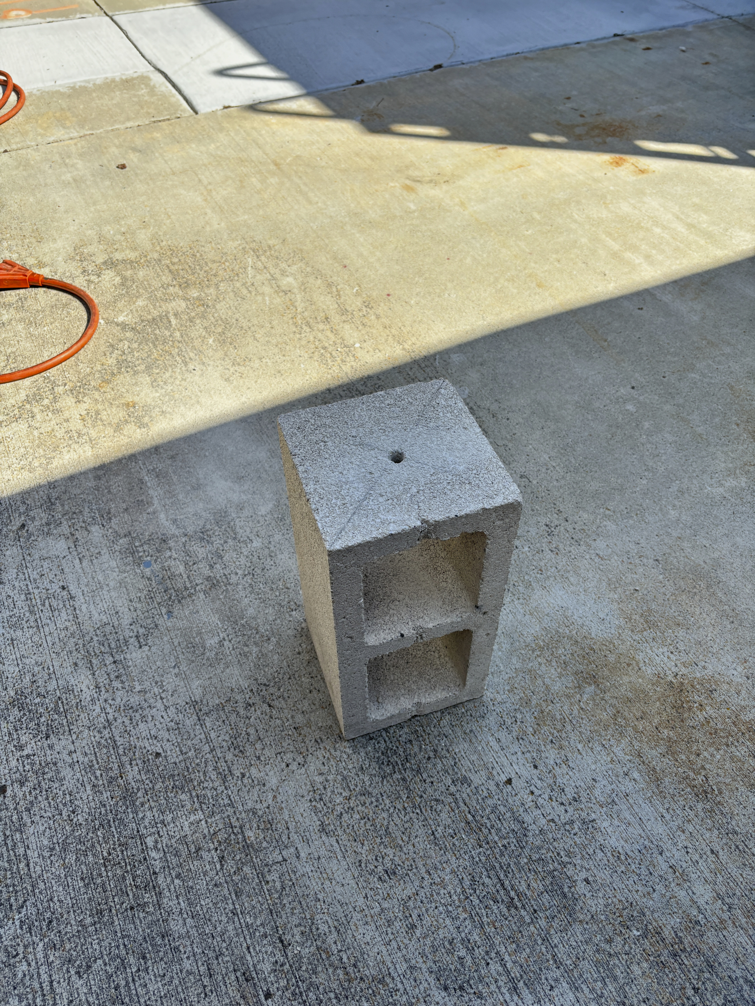
The first problem to solve is how to attach the pier adapter to
the column. The adapter we purchased has one 3/8" mounting
hole in the center of the adapter. So, we drilled on 3/8"
hole in the center of the top block to allow passage for the 3"
mounting bolt. Diagonals were marked and the hole was
drilled. But, since we were using a hammer drill, the bit
skipped early in the process resulting in an off-center
hole. Happily, the final performance of the mount was not
impacted. Final level of the adapter will be achieved
using the 3-bolt leveler built into the adapter.
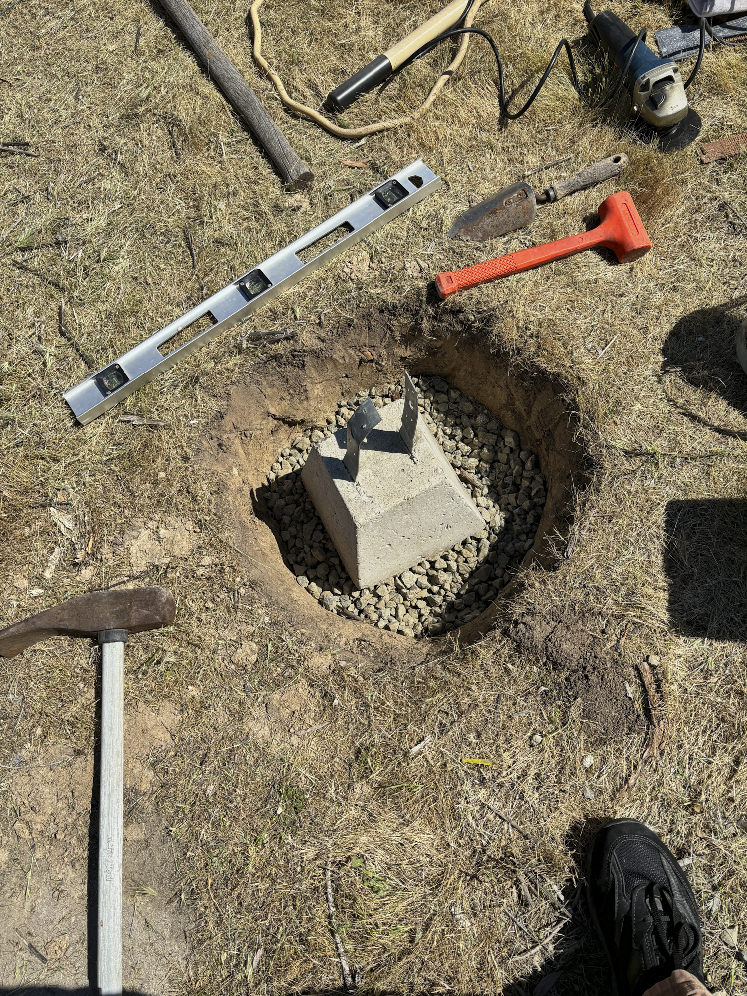
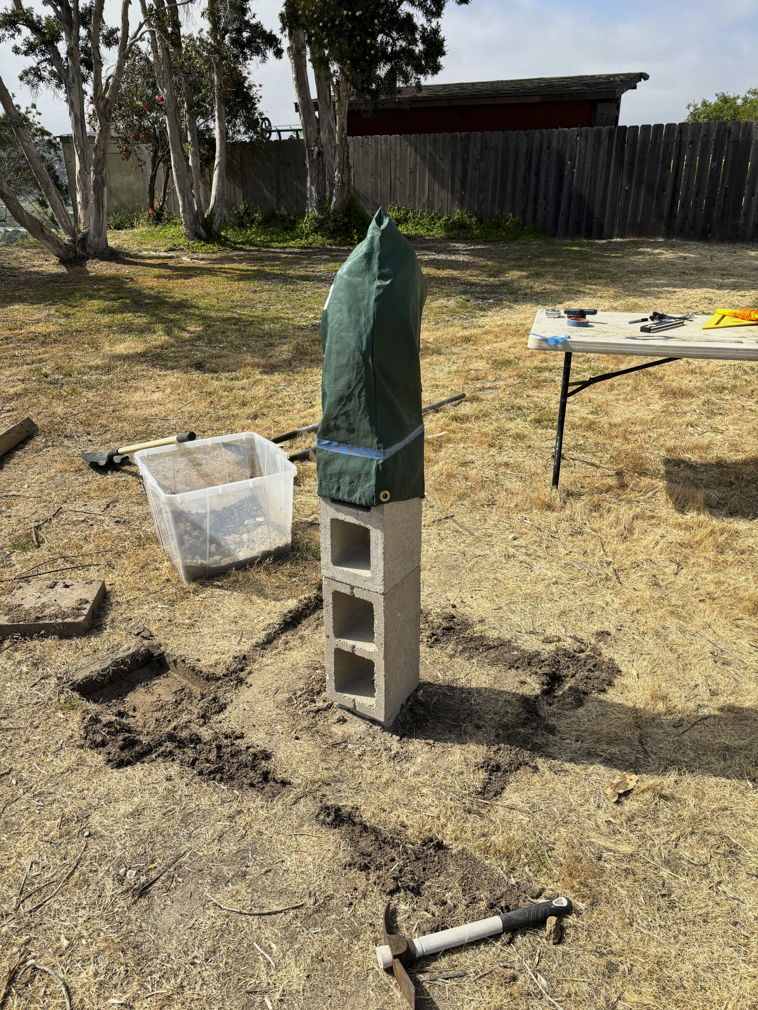
Next, a hole was dug at the selected location deep enough to
allow burying the post pier and accommodate a thick layer of
gravel. Using the gravel as the base layer makes leveling
easier and does not require the bottom of the hole to be flat or
level. Once the hole was big enough, gravel was added and
a test fit of the post pier was performed. The gravel
was adjusted and tamped to bring the pier into an
acceptable position. When level was established, soil was
returned to the hole and compressed via tamping with a large
hammer. The returned soil was kept below the top of the
pier block. A cutoff tool and angle grinder were used to
cut off the mounting straps and insure that the top of the pier
was smooth and prepared for the gluing of the column blocks.
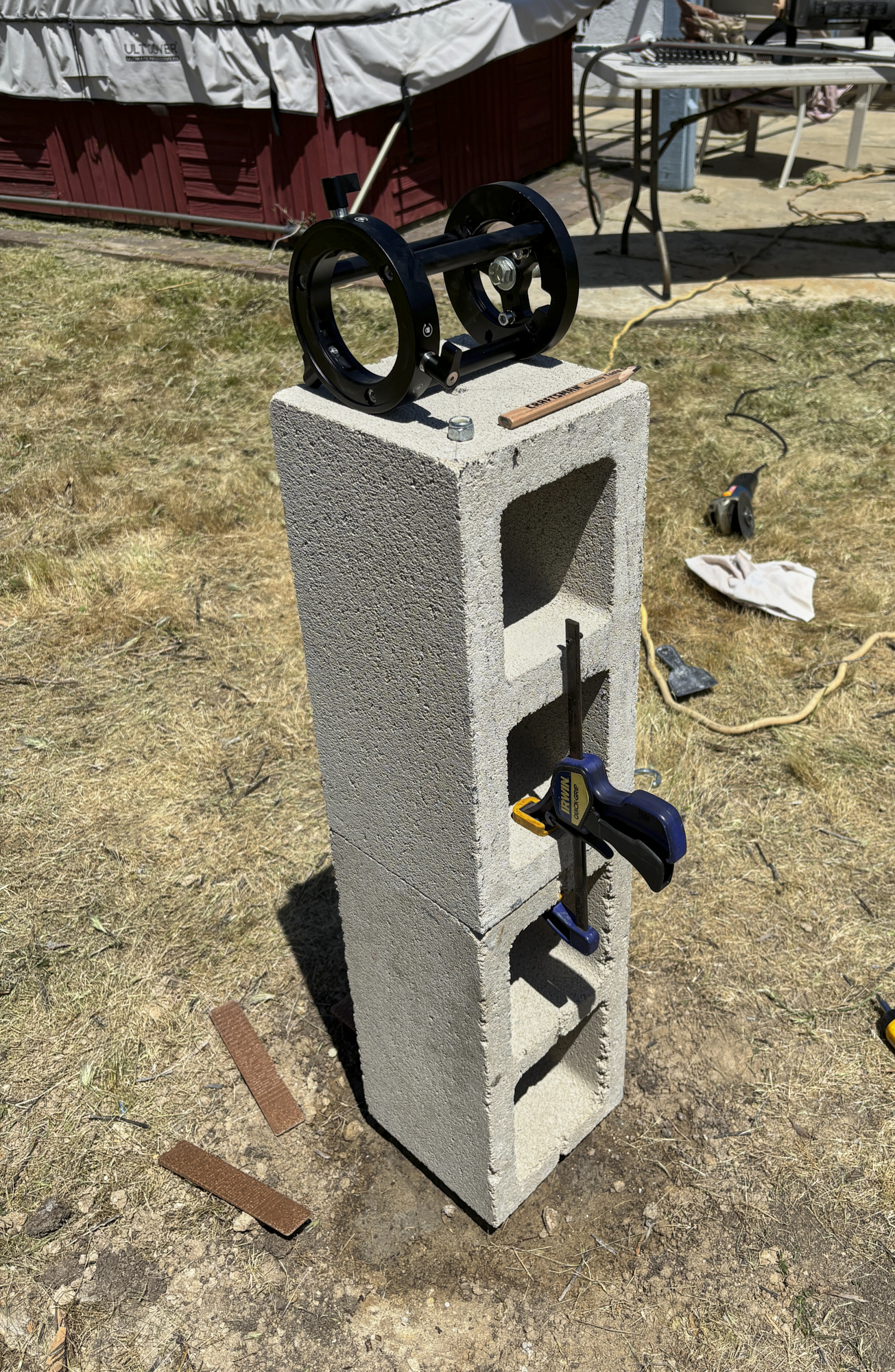
A test fit of the column blocks on the pier base was performed
and shimming was estimated. This step is easier as a two
person process. The level of the top (mounting) surface of
the column was adjusted with shims until an acceptable result
was achieved. Once the shim requirements and locations
were determined, a big goober of adhesive was applied to the
clean, dust-free surface of the pier block and the bottom of the
column block and the components were mated. The the final
shimming was installed. Glue was applied to the top of the
base column block and some clamps were added to prevent
slippage. Level was re-checked and shims were adjusted
until acceptable. Then, it is "Miller Time" until the
adhesive cures (4 hours minimum, see the package label).
In the photo above, the pier adapter is visible (black metal
cage).
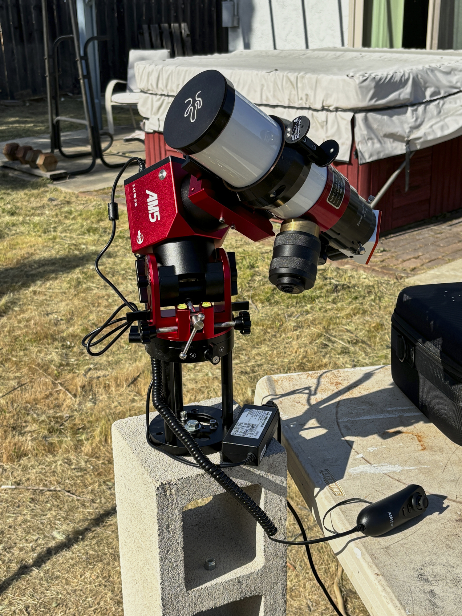
The next day, we attached the pier adapter and did some
tests on the assembly. The column was rock-solid as
expected and had not shifted from level. We cut off the
exposed shims with metal shears to provide a cleaner look.
The adapter was attached to the column with the 3/8" bolt and
the fine leveling was performed with the tripod screw
adjustments. Final adjustment of the orientation of the
tracking mount would take some time and an accurate estimate of
true north. Typically, this is performed with a
special-purpose tool or a process known as "drift
alignment". Both of these techniques require visibility of
Polaris the pole star. In San Diego, good visibility at
night is a rare thing, so a more conventional approach was used
based on a magnetic compass. A usable alignment was
finally achieved, but a more precise result will be needed for
any star tracking.
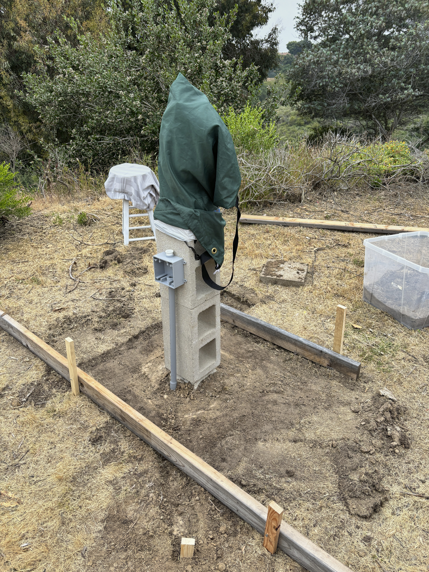
After using the mount for a few days and noting our movement
patterns around the mount, we concluded that a skirt was
required for dust control. So, we planned to pour a
concrete slab at the base of the column and install provisions
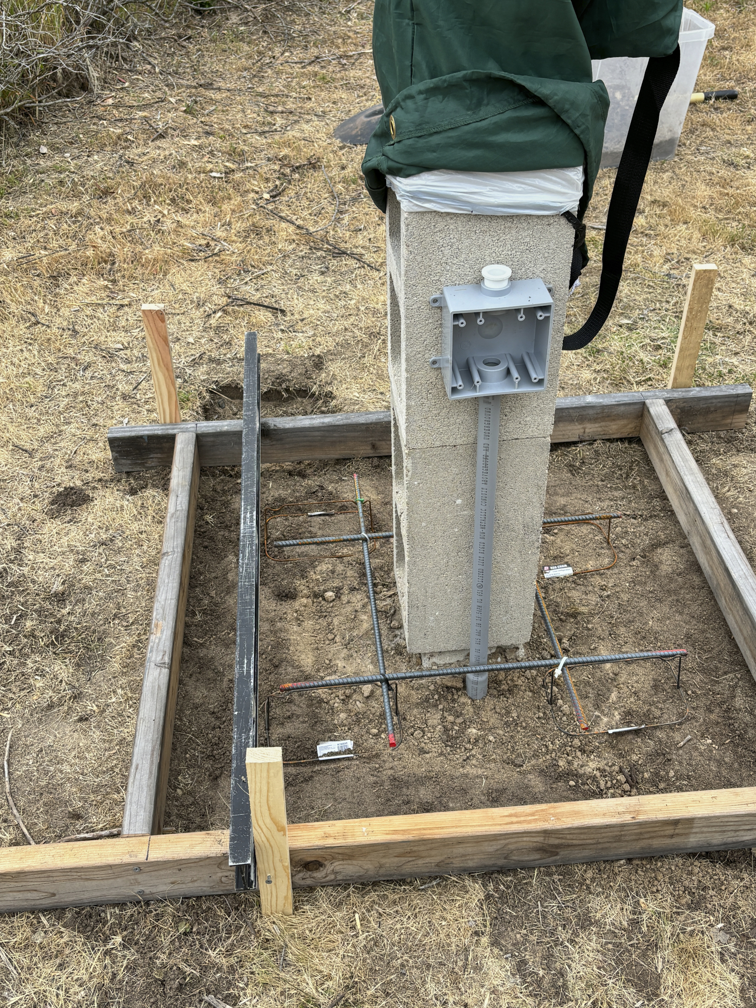
for electrical service at the pier. Above, rough outlines
of the form are marked in the soil.
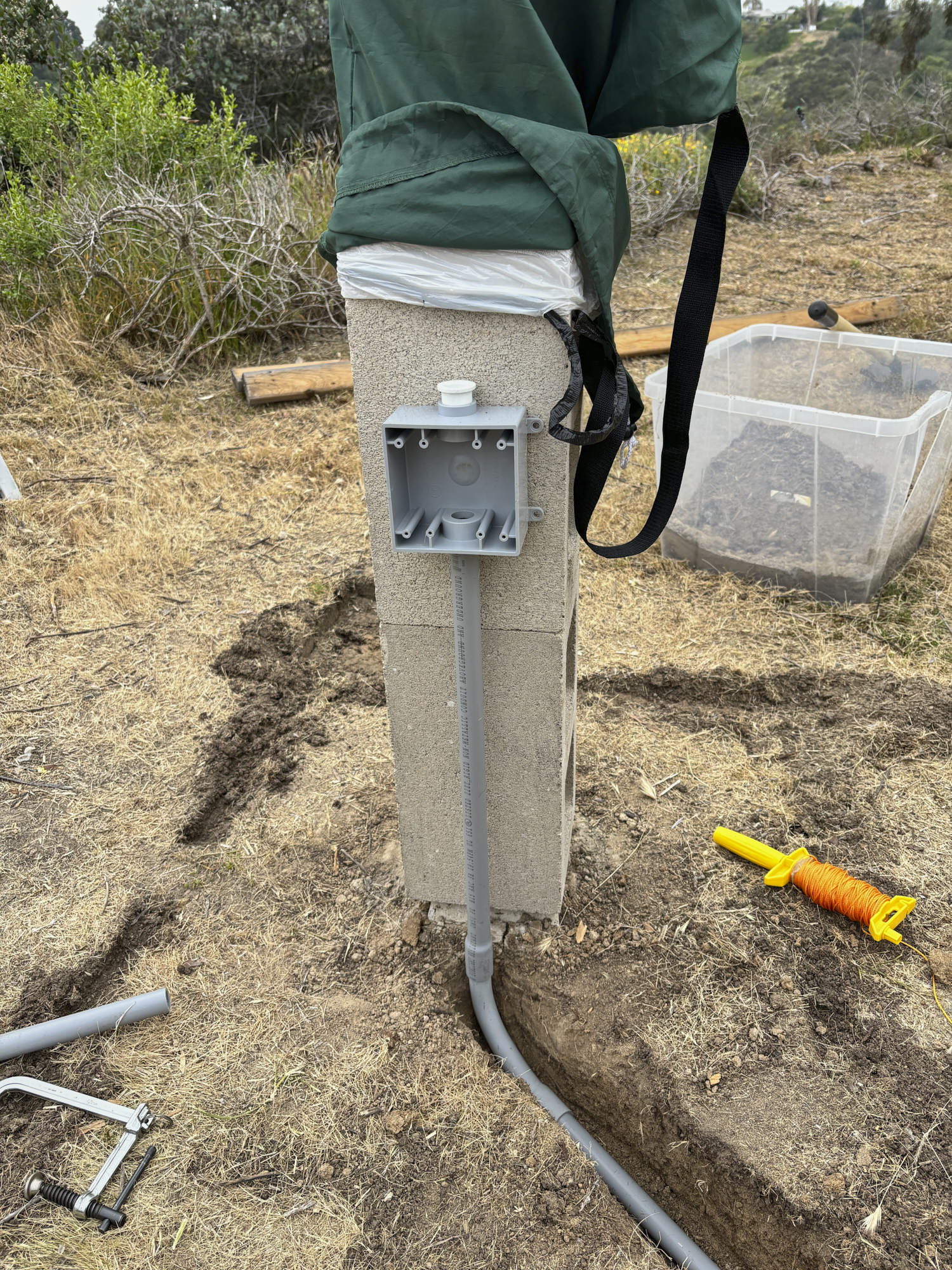
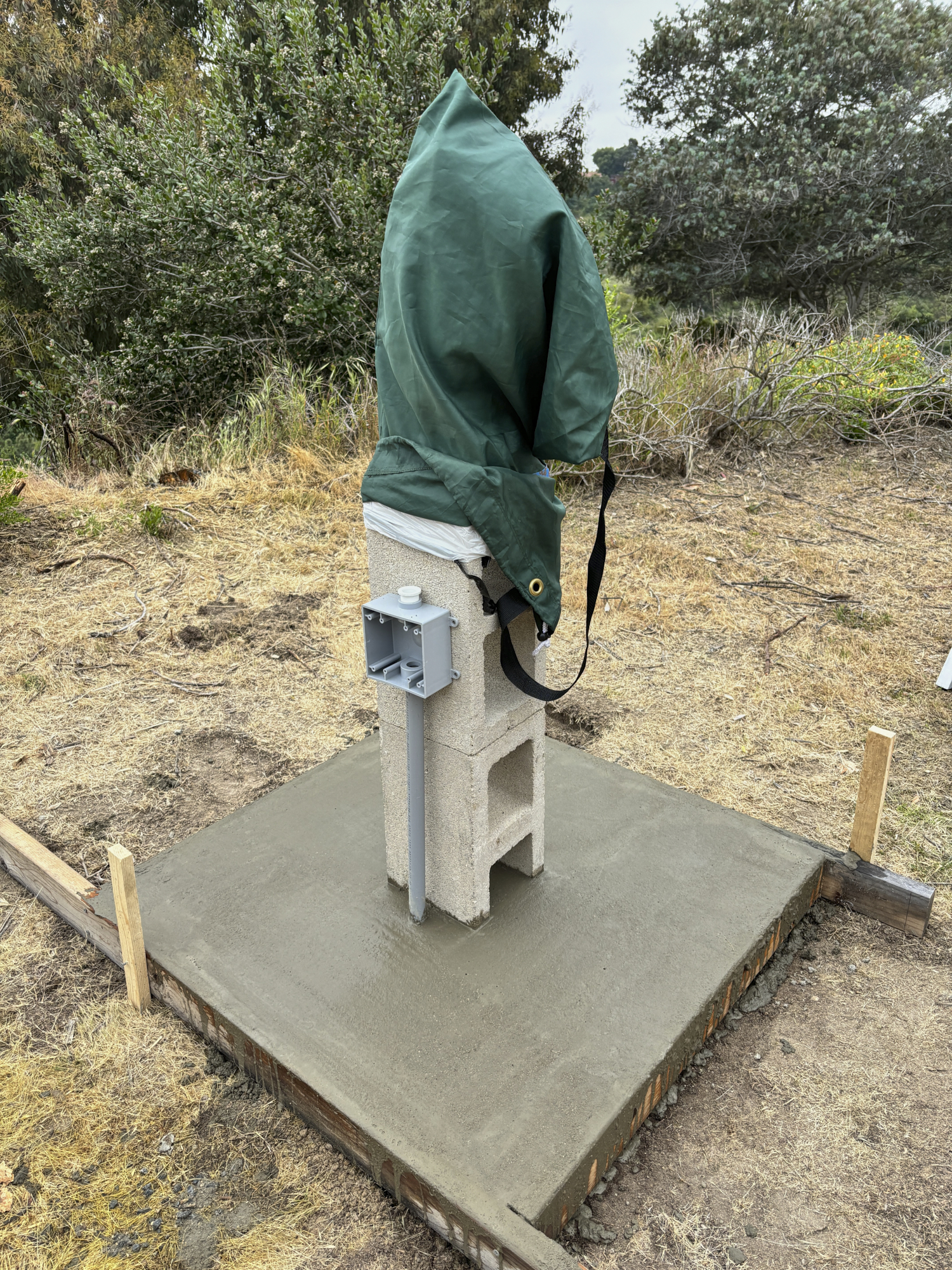
Back to the Home Depot for
electrical conduit and a 2-gang outlet box. Trenches
were dug and conduit was installed. The outlet box was
attached to the column using construction adhesive and clamped
until the adhesive cured.
One the adhesive was cured, the trench was refilled and packed
and the forms were placed using stakes to hold them in
position. Look carefully at the photo above: the post pier
is visible. This junction will be encased in the final
slab.
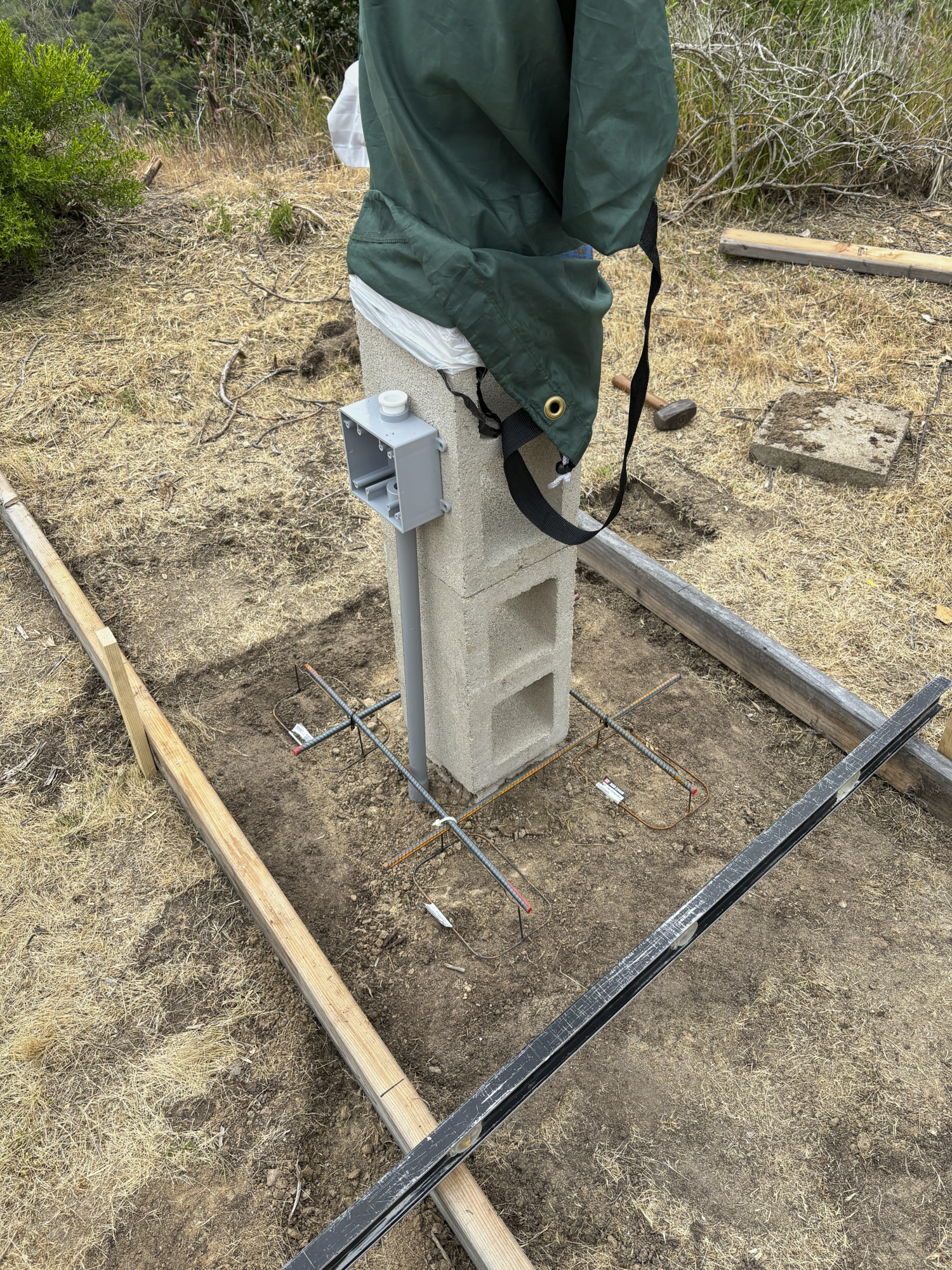
We got some short rebar pieces and rod chairs to suspend them in
the concrete. The components were positioned and held
together using small zip ties. Form sides were checked for
levelness.
Connecting form members were cut to fit and installed and
levelness was re-checked.
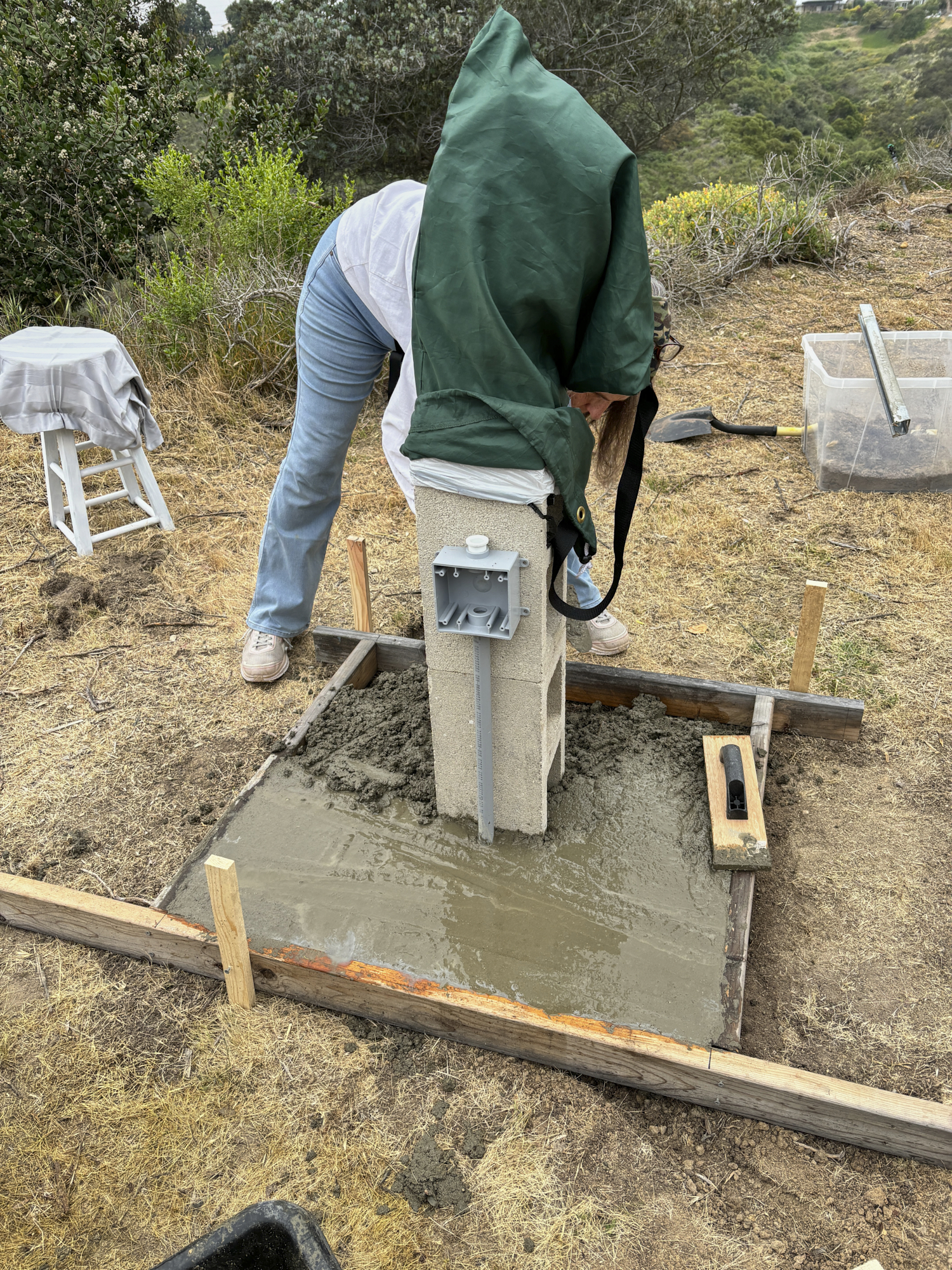
Very few actions are as much fun as manually mixing and pouring
concrete. I say this tongue in cheek as it is hard, dirty
work. Fortunately for us, it was overcast and cool making
the burden easier to bear. I mixed and shoveled the
mixture into the forms and Kathleen packed and floated the
surface.
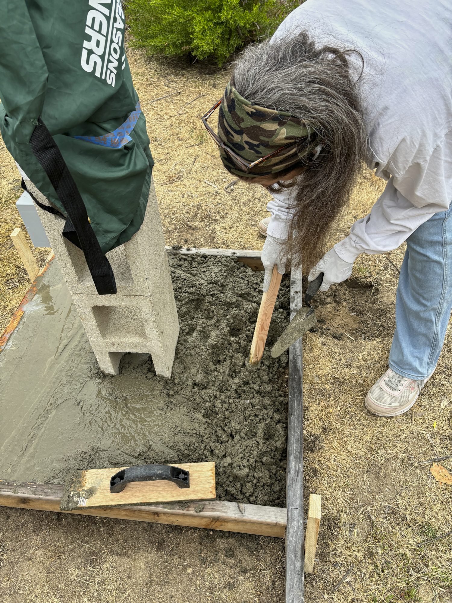
One bag of concrete left to mix and pour.
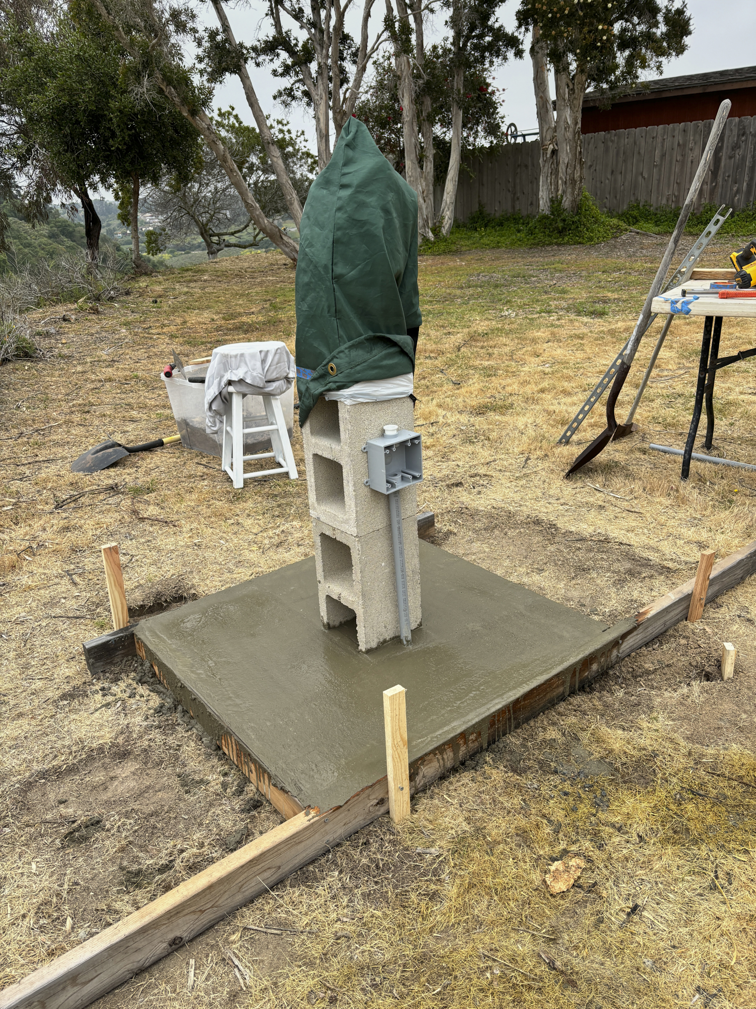
The finished product pending a final skimming of the surface for
smoothness.
We will let this cure for a few days before busting off the
forms. We'll take the extra soil that came from the
excavation and put it around the perimeter of the slab and clean
up any excess concrete that was spilled on the "grass" area.
We are confident that this
permanent mount will improve the quality of our
astro-photos. That said, no amount of construction will
improve our coastal weather. When the weather clears, we
will use the drift alignment technique for precise alignment of
the mount as described on ExploreScientific
Back to Bill Caid's Home Page
Copyright Bill Caid 2024. All rights
reserved.