Astrophotography
Equipment
The "kit" that gets
the job done
All photos, Copyright (C) Bill Caid, 2013,
2017. All rights reserved.
Back to Astrophotographs
Equipment
I have a variety of
digital cameras, but only the "bigger" SLR-style cameras are
applicable to astrophotograpy (AP) tasks. There are
several reasons for this observation including the ability to
use a remote control for the shutter and the availability to set
the camera in a manual mode that allows taking extended duration
photos. Generally, but not always, the DSLR cameras meet
these criterion.
For the last 12+ years
I have been using Canon equipment and currently have 3 Canon
bodies: a 20D 8mp, a 1Ds Mark 2 16mp and a 1Ds Mark 3
21mp. The Mark 2 and Mark 3 bodies are full-sized (AKA
very heavy) pro cameras while the 20D is a consumer-grade
body. I have only used the Mark 2/3 because my remote
control dongle matches these bodies and provides accurate
interval and exposure control.
In addition, I recently
purchased an Olympus OM-D EM-5 16mp camera. The EM-5 is
based on the micro four thirds (MFT) format and has a number of
endearing attributes that were both unknown and unexpected when
I bought the camera. First, the MFT design does not use a
mirror in the camera. The standard SLR (single lens
reflex) camera has a diagonal mirror that is in the optical path
that reflects the light through the lens to the user's eye
during the framing and focusing process. This mirror is
retracted when you trigger the shutter producing the loud
characteristic shutter noise associated with the SLR-type
camera. The MFT design eliminated the mirror and instead
uses the imaging chip in real time to present what the lens sees
to the user via either the rear LCD display or via a smaller LCD
display located inside the camera that provides a so-called
Electronic View Finder (EVF). To the casual observer,
these MFT cameras look just like a DSLR except that the eye
piece is acting as a miniature video display. The
consequence of this design is two-fold. First, it makes
the form factor of the camera smaller and thus lighter in weight
and more portable. Second, and more importantly for this
application, the physical distance from the lens mating flange
to the focal plane is quite a bit shorter thus allowing the use
of a wide variety of legacy lenses by using a simple mechanical
adapter that provides an offset equal to this difference in
distance (and the mounting lugs). Because of this, there
are a number of excellent used lenses that are available "for
cheap" that prior could only be used on the native
cameras. For instance, I have several Zeiss lenses
designed for the Leica M-mount. With a simple mechanical
adapter that provides the correct offset and is machined for the
M-mount lugs, I can use these lenses on the Oly. And it
produces excellent results, but only in manual focus and manual
aperture modes.
The second remarkable
quality of these MFT cameras is that manual focusing is done in
real time using the EVF or LCD panel on the back of the
camera. These displays show exactly what the camera will
record when the shutter is triggered, thus allowing viewing of
the focus and exposure parameters easily. Focusing old SLR
film cameras or even newer DSLR cameras without the live view
capability was a bitch and required many wasted shots or
addition of an extra prism-based focusing aid to get it correct
with fewer tries. The crux is attainment of critical focus
and as the photos will show, it is harder, or impossible, to
reach critical focus without using some kind of aid. The
LCD panel provides this aid and it is built into the design of
the camera.
Generally, to do any AP
shots of stars, you have to use some kind of tracking mount or
another method of compensating for the movement of the stars
relative to the earth. The standard way to do this is to
use a tracking mount. More specifically, an equatorial
mount where the rotational axis of the mount is parallel to the
earth's rotational axis. These mounts turn the
telescope/camera at the same rate as the sky causing the stars
to "hold still" while you take a long exposure photo. The
longer the photo, the more light that can be gathered.
But, the longer the photo, the higher the chance for errors in
your alignment. This process of alignment is generally
called "polar alignment" because the scope is pointed at the
pole star, Polaris.
As it turns out Polaris
is not really at the celestial pole. It is close, but not
close enough for taking long photos. Consequentially, the
process of achieving a good polar alignment becomes quite a bit
more complex requiring both optical aids like a special aiming
scope and a mechanical procedure for fine adjustment. In
early 2013 I purchased an Astrotrac mount that provides both
portability and low tracking error. This assumes, of
course, that you adhere to the alignment process with high
fidelity and attention to detail.
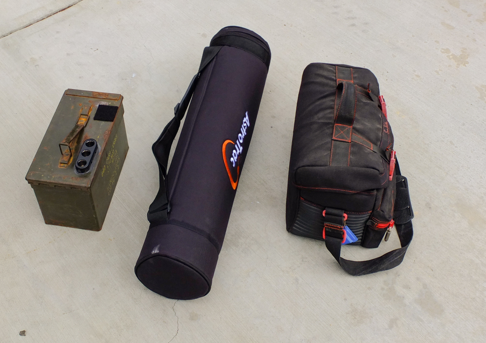
The Astrotrac mount
comes in a compact carrying case to provide high
portability. I had to augment the basic tube with a
"battery box" and a VCR bag that contains the extras
needed. Note the 3 plugs on the top of the battery box.
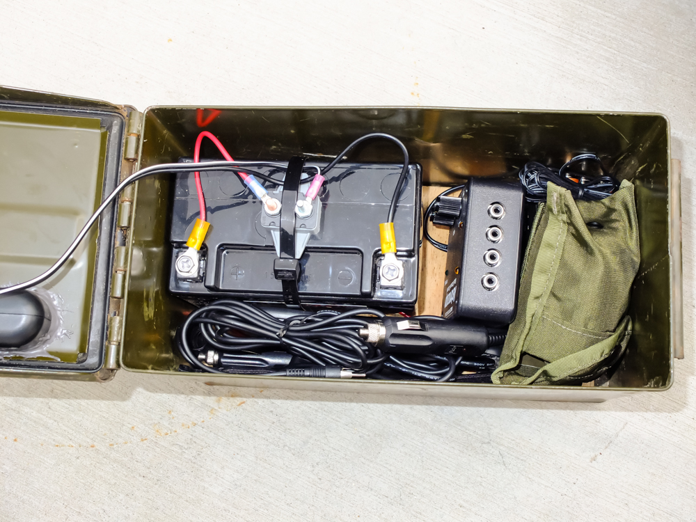
I fabricated the
battery box from a jet ski battery, an ammo can and a 3-plug
cigarette lighter socket. The can also stores the lens
heater (to prevent dew from collecting on the lens), extra
wires, a magnetic compass for coarse alignment of the mount
and a small plug-in light. The Astrotrac comes with a
small AA battery array that powers the mount. But, extra
12V is needed for other things and the Astrotrac comes with a
cable set that allows using a cigarette plug, so the decision
to make an all-in-one was easy.
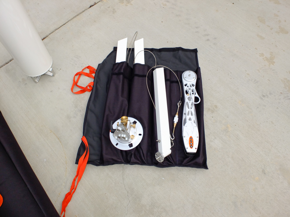
Inside the tube is a
roll that contains the tracker head, 3 legs with guy wires,
turn buckles and screw feet. The adjustable screw feet
are used for for leveling the pier. The mounting wedge
is stored upside down at the end of the tube. Note the machined
attachments on the bottom for the support legs.
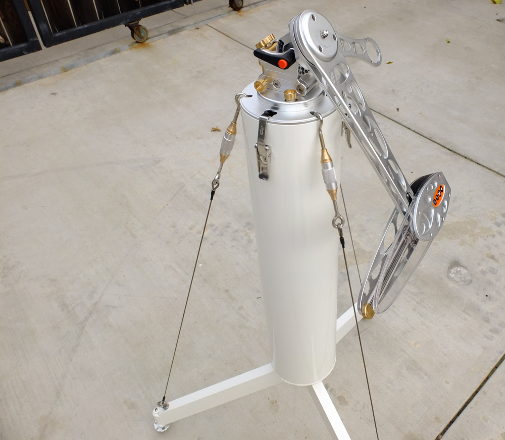
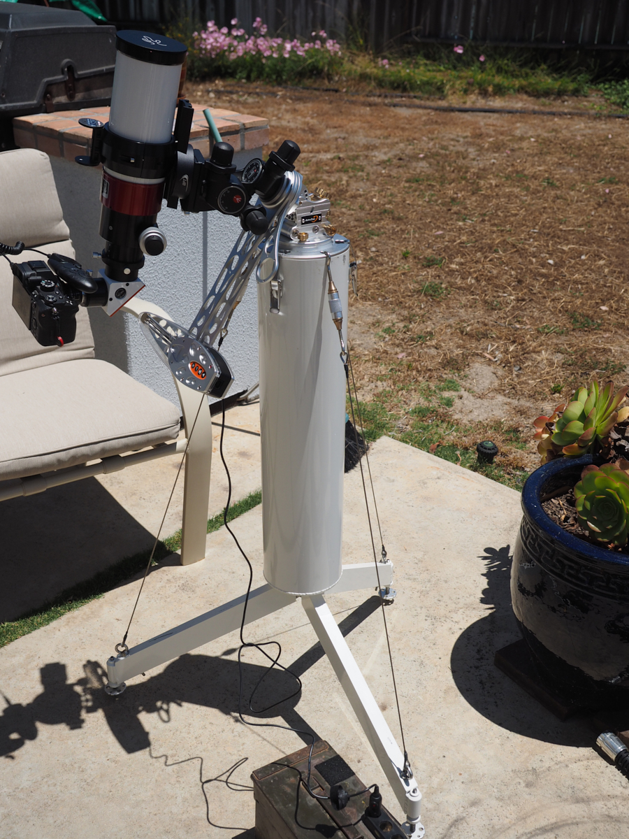
The wedge is placed
on the open end of the tube and secured with the
latches. The legs are then plugged onto the machined
attachments, the guy wires are attached to holes in the wedge
and the turn buckles are tightened until sufficiently taught.
The tracker head is attached to the wedge mount via stainless
steel socket head cap screws using the 3 holes in the
wedge. The tracker provides a 3/8" screw mount for
attaching standard tripod heads. Your camera is then
connected to the tripod head.
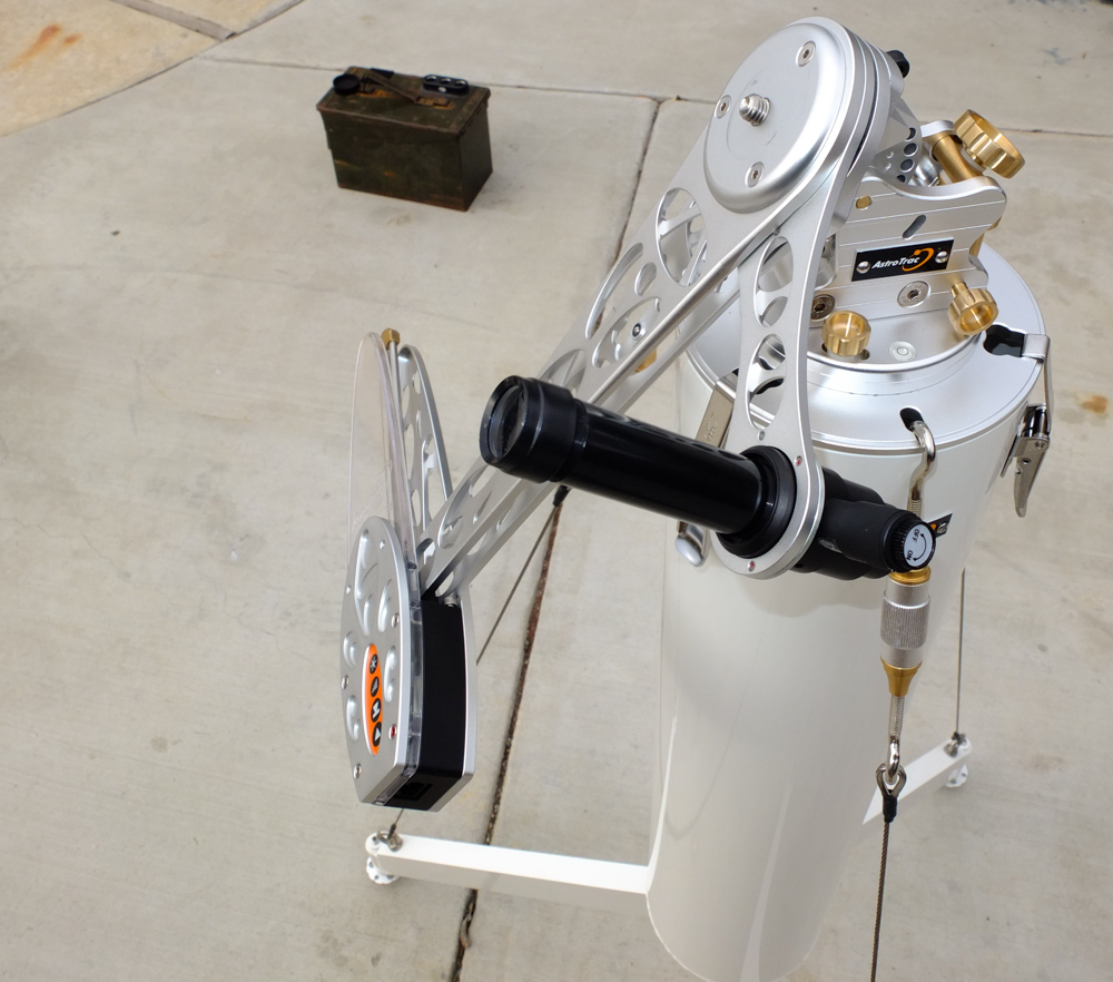
When the
mount is deployed, the screw feet are used to level the head of
the pier using the bubble level built into the base of the
wedge. It should be noted that
the design of the Astrotrac allows filling the main tube with
ballast such as bags of sand, gravel, rocks or a water bladder
to provide extra stability for the mount. In the
photo above, the tracker head is deployed in the correct
position for the northern hemisphere; if tilted to the opposite
side, it would track for the southern hemisphere. The
tracking head is attached to the 12V supply and it is ready to
go. A microprocessor in the head controls the rotation of
the lead screw. The lead screw then separates the 2 arms
of the tracker providing rotation for the head of the mount.
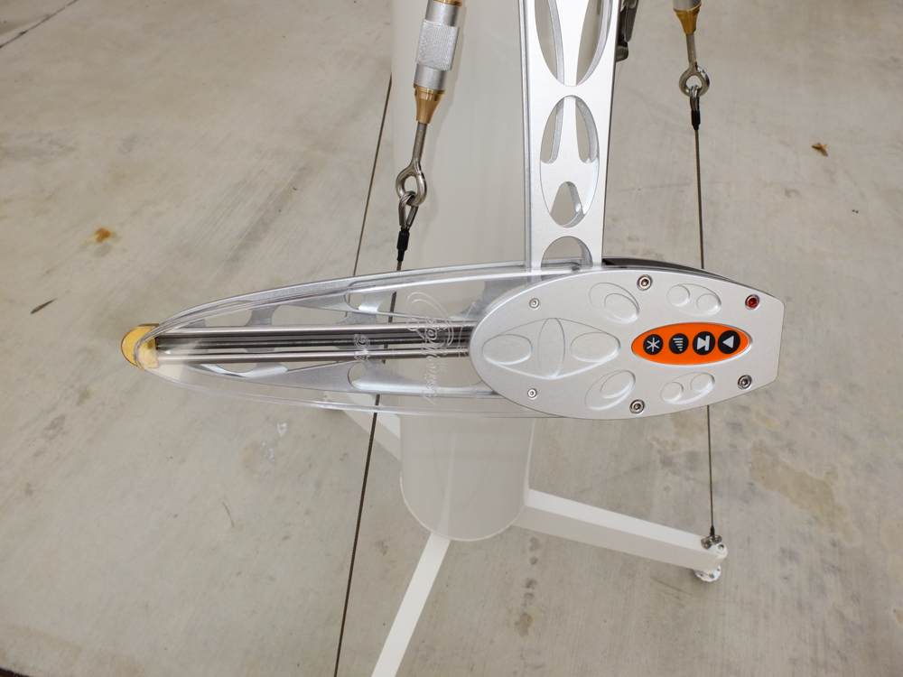
In this
photo, the polar alignment scope can be seen. The swing
arm can be rotated to provide a clear view and the scope is held
to the arm by a magnetic attachment. The rotary switch on
the scope controls the illumination of the reticle used for
sighting.
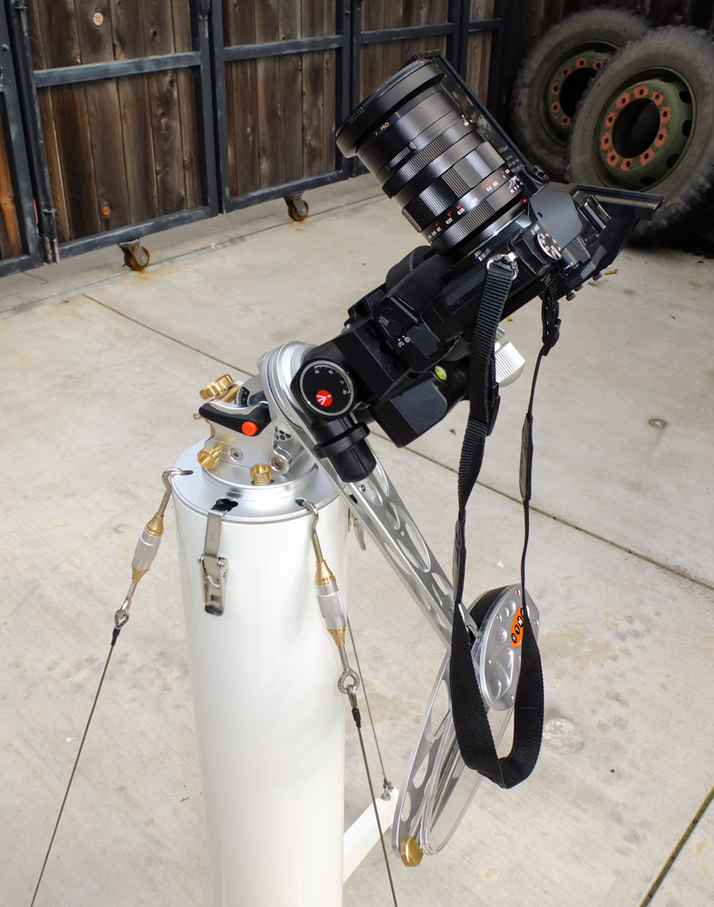
I use a gear-drive tripod head attached to the tracker to
provide fine positioning control. A standard dove tail
mount was attached to the removable portion of the tripod
head. The camera and sighting tool (a Telrad 1X LED sight)
are attached to the dove tail bar. The tripod head and
camera are shown in a south-facing configuration in the photo
above.
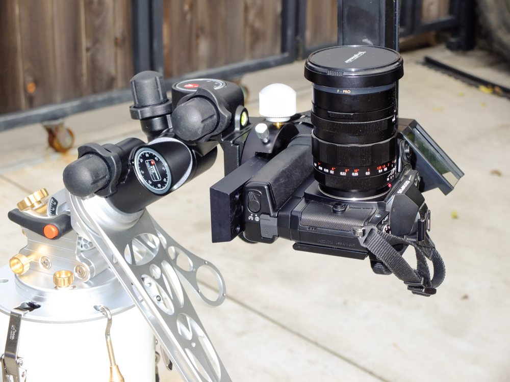
The tripod head has to be rotated 180 degrees and the dove tail
bar reversed to allow looking at the zenith. The knobs of
the head interfere with the arms of the Astrotrac and therefore
the head has to be rotated. The camera shown is the
Olympus OM-D EM-5 With Voightlander f/0.9 17.5mm lens.
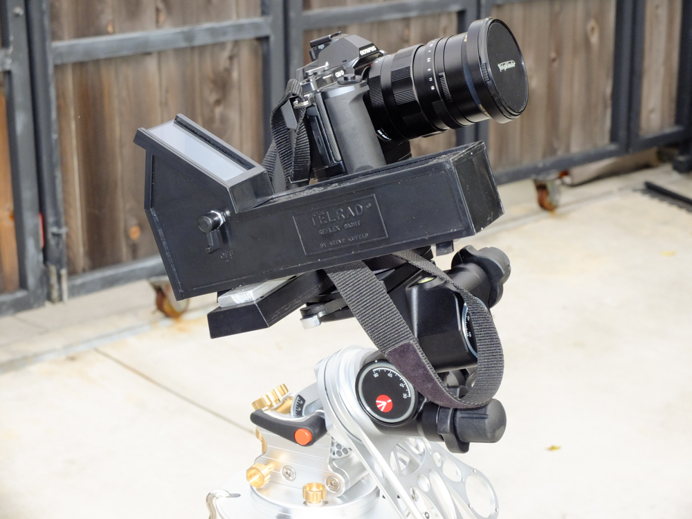
A reversal of the zenith position will allow a view of the
southern sky. The Telrad LED sight is clearly visible in
the photo above.
The Astrotrac head uses
a tangent approach to tracking. Inside the head is a lead
screw that is controlled by a stepper motor and a
microprocessor. The processor knows where it is relative
to the length of the screw and adjusts its rate to compensate
for tangential error. This tracker has very low periodic
error, but can only track for about 2 hours before needing to be
reset as that is the length of the lead screw. So far,
this time has not proven to be a limitation.
Lunt 60mm (500mm focal length) Solar Scope with Sony A7RM2 mounted
on Astrotrac mount.
Back to Astrophotographs